Projection system

Active Publication Date: 2015-05-07
QISDA OPTRONICS (SUZHOU) CO LTD +1
View PDF4 Cites 3 Cited by
  • Summary
  • Abstract
  • Description
  • Claims
  • Application Information

AI Technical Summary

Benefits of technology

The present invention provides a projection system that can direct light from multiple sources through a transmission surface and a reflection surface to create a more even and bright image. By controlling the ratios of the two surfaces to the panel width of the image modulation device, the system can maintain a consistent light output and achieve better homogenization of the image. This design solves issues with conventional light collection for multi-source projections that do not consider light-out distribution.

Problems solved by technology

In generally, the increase of illumination is achieved by employing light sources with higher power; however, a higher-power light source may result in a higher temperature, which may consequentially affect the light-emitting efficiency or even be detrimental to the light source lifespan.
However, the lights emitted from the more than one light source may not have a certain homogenization and present a specific distribution characteristic (e.g., a Gaussian distribution); and conventionally, the light collection design for multi light sources are implemented as having their light-output directions toward the light-guiding rod only but without considering the specific light distribution.
As a result, the light projected onto an image modulation device from a light-output end of the light-guiding rod may not be sufficiently homogenized, and accordingly the brightness of the projected image may have poor uniformity.

Method used


Image

  • Projection system
  • Projection system
  • Projection system

Examples


first embodiment

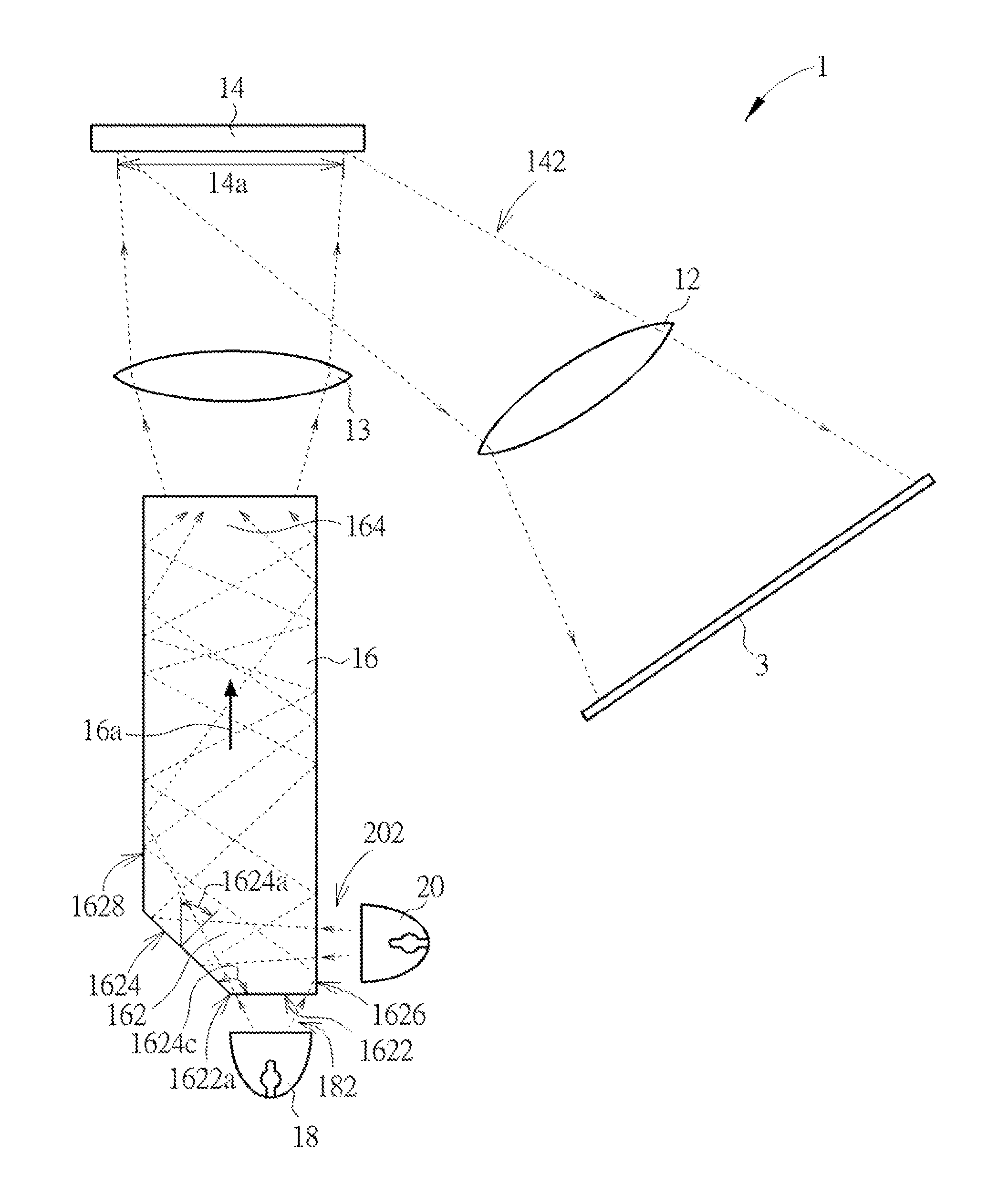
[0017]FIG. 1 is a schematic view of a projection system in accordance with the present invention. As shown in FIG. 1, the projection system 1 in the present embodiment includes a projection lens 12, an image modulation device 14, a light-guiding rod 16, a first light source 18 and a second light source 20. The first light source 18 and the second light source 20 are configured to generate a first light 182 and a second light 202, respectively. Once receiving the first light 182 and the second light 202, the light-guiding rod 16 homogenizes and mixes the first light 182 and the second light 202 and then transmits the homogenized and mixed light onto the image modulation device 14. The image modulation device 14 receives the light from the light-guiding rod 16 and forms an image light 142 corresponding to image data. The projection lens 12 projects the image light 142 onto a screen 3 thereby forming an image.

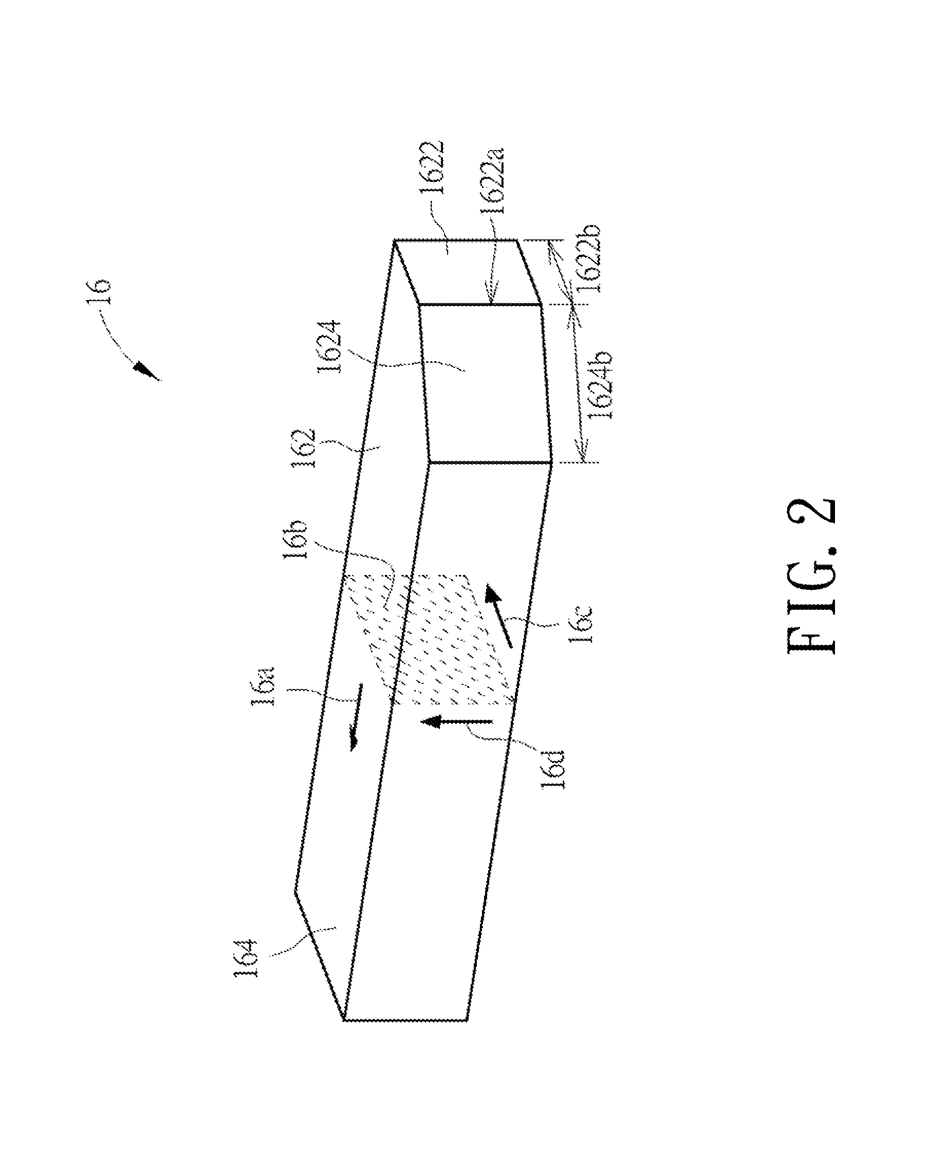
[0018]Next, please refer to FIG. 2, which is a perspective view of a light-gu...

third embodiment

[0027]In the projection system 5 of the third embodiment, the first reflection surface 5624 and the first side surface 5628 are formed on the same side of the transmission surface 5622, and the second reflection surface 5626 and the second side surface 5630 are formed on another same side of the transmission surface 5622; however, the present invention is not limited thereto. FIG. 8 is a schematic view of a light-guiding rod in accordance with another embodiment of the present invention. As shown, the light-guiding rod 57 in the present embodiment of FIG. 8 has a structure similar to that of the light-guiding rod 56 shown in FIG. 7. The main difference between the two light-guiding rods is that in the light-guiding rod 57, both of the angle 5624c, formed between the first reflection surface 5624 and the transmission surface 5622, and the angle 5626c, formed between the second reflection surface 5626 and the transmission surface 5622, are within a range from 90 degrees to 180 degrees...


PUM


Abstract

A projection system includes a projection lens, an image modulation device, a light-guiding rod and two light sources. The light-guiding rod is defined with an axial direction and has a first end and a second end. The first end has a transmission surface and a reflection surface. The ratios of the widths of the transmission and reflection surfaces to the panel width of the image modulation device are 0.13˜0.35. The lights of the first and second light sources are incident into the light-guiding rod through the transmission surface and onto a first side surface and reflected into the light-guiding rod through the first reflection surface, respectively. The light-guiding rod homogenizes the incident lights and transmits the homogenized light to the image modulation device through the second end thereby forming an image light. The projection lens projects the image light.

Description

FIELD OF THE INVENTION[0001]The present invention relates to a projection system, and more particularly to a projection system having multiple light sources.BACKGROUND OF THE INVENTION[0002]Most of the current project systems have single light source. Thus, to increasing the brightness of projected images, there is no much choice but to increase the illumination of a light source. In generally, the increase of illumination is achieved by employing light sources with higher power; however, a higher-power light source may result in a higher temperature, which may consequentially affect the light-emitting efficiency or even be detrimental to the light source lifespan. To overcome this issue, multi-light-source projection system is introduced in current market now. In a multi-light-source projection system, the lights generated by more than one light source are directed into one signal light-guiding rod first and then are mixed by the light-guiding rod thereby increasing the brightness ...

Claims


Application Information

Patent Timeline
IPC IPC(8): G03B21/20G03B21/00
CPCG03B21/208G03B21/005G03B21/2013G03B21/2066G03B33/06
Inventor LIN, MING-KUENWU, TSUNG-HSUN
Owner QISDA OPTRONICS (SUZHOU) CO LTD
Why Eureka
Try Eureka