Projection system
a projection system and projection system technology, applied in the field of projection systems, can solve the problems of poor uniformity of projection images, affecting the life of light sources, and high temperature, and achieve the effect of high homogenization
- Summary
- Abstract
- Description
- Claims
- Application Information
AI Technical Summary
Benefits of technology
Problems solved by technology
Method used
Image
Examples
first embodiment
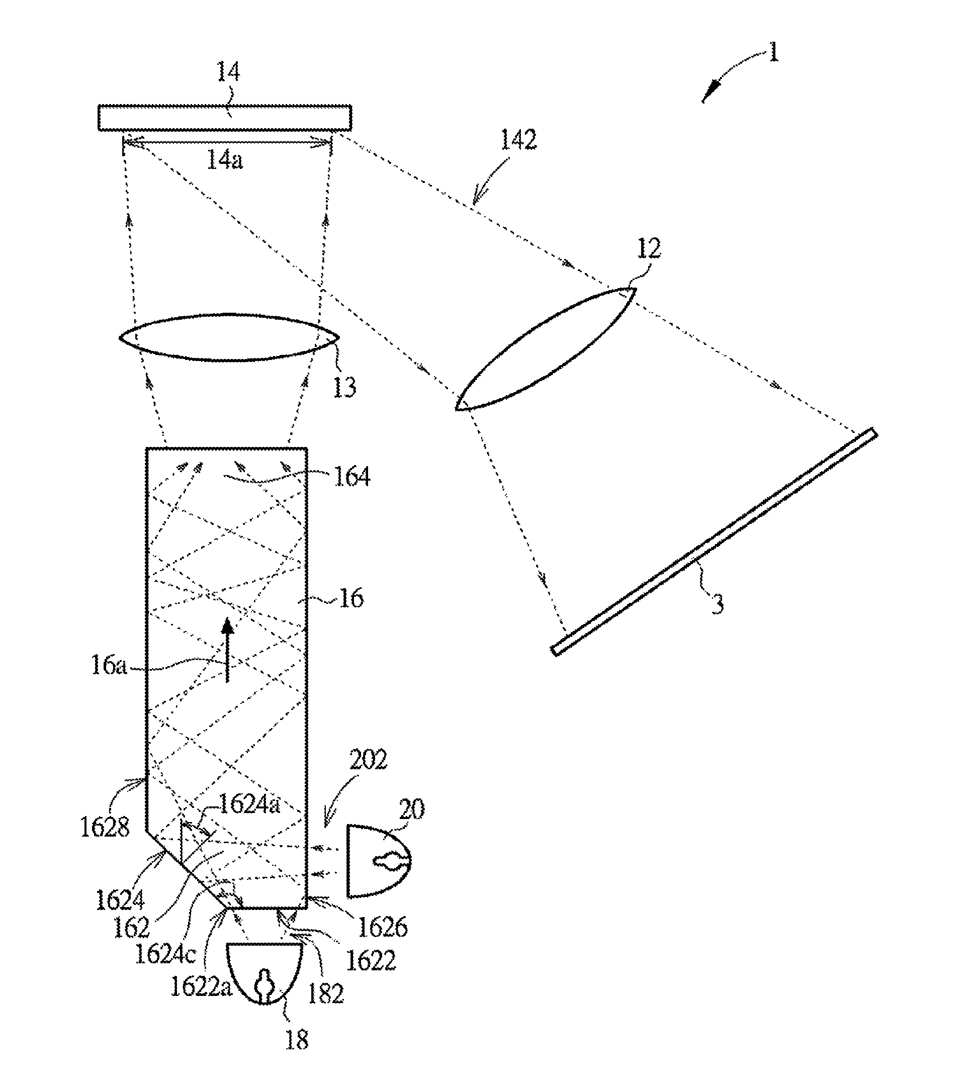
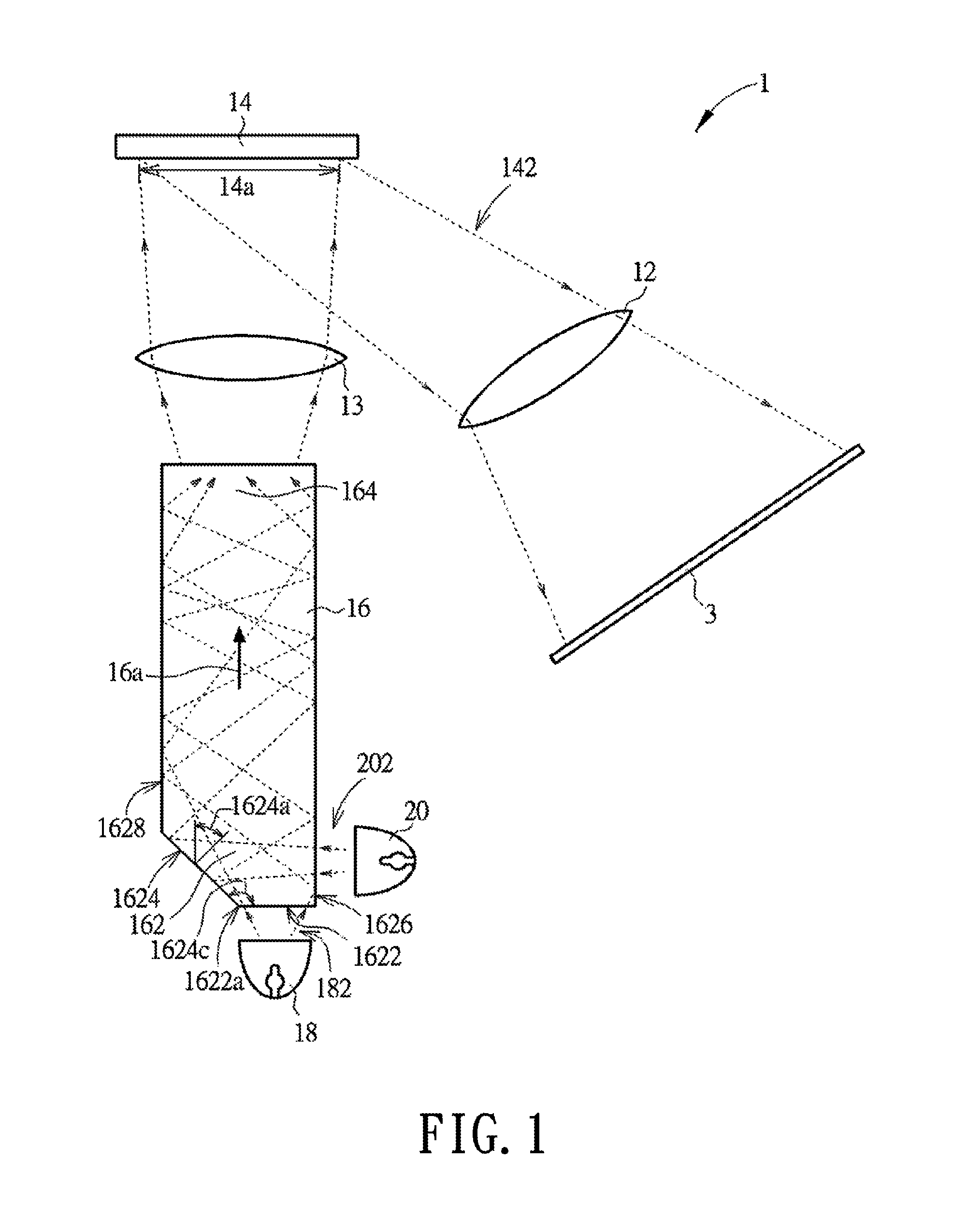
[0017]FIG. 1 is a schematic view of a projection system in accordance with the present invention. As shown in FIG. 1, the projection system 1 in the present embodiment includes a projection lens 12, an image modulation device 14, a light-guiding rod 16, a first light source 18 and a second light source 20. The first light source 18 and the second light source 20 are configured to generate a first light 182 and a second light 202, respectively. Once receiving the first light 182 and the second light 202, the light-guiding rod 16 homogenizes and mixes the first light 182 and the second light 202 and then transmits the homogenized and mixed light onto the image modulation device 14. The image modulation device 14 receives the light from the light-guiding rod 16 and forms an image light 142 corresponding to image data. The projection lens 12 projects the image light 142 onto a screen 3 thereby forming an image.
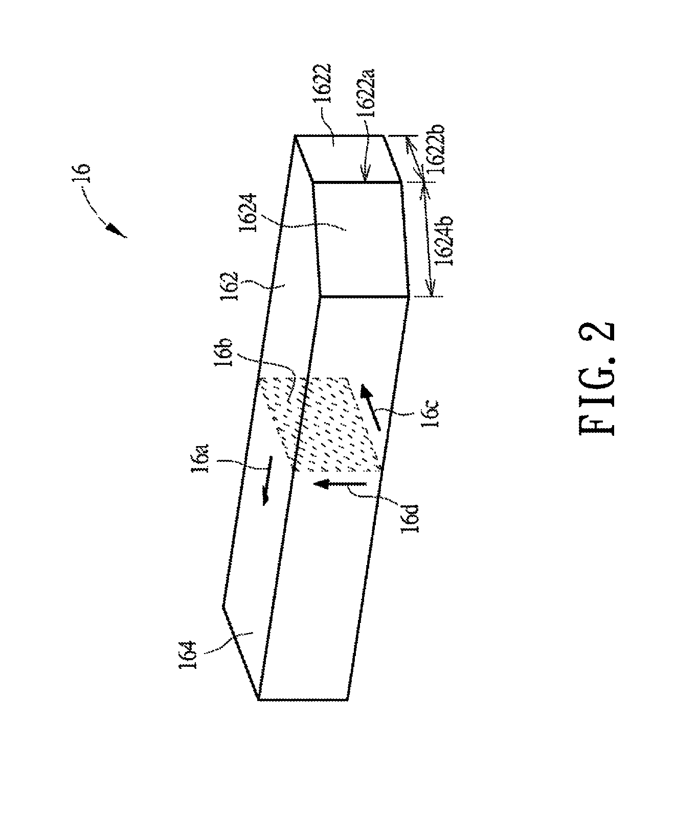
[0018]Next, please refer to FIG. 2, which is a perspective view of a light-gu...
third embodiment
[0027]In the projection system 5 of the third embodiment, the first reflection surface 5624 and the first side surface 5628 are formed on the same side of the transmission surface 5622, and the second reflection surface 5626 and the second side surface 5630 are formed on another same side of the transmission surface 5622; however, the present invention is not limited thereto. FIG. 8 is a schematic view of a light-guiding rod in accordance with another embodiment of the present invention. As shown, the light-guiding rod 57 in the present embodiment of FIG. 8 has a structure similar to that of the light-guiding rod 56 shown in FIG. 7. The main difference between the two light-guiding rods is that in the light-guiding rod 57, both of the angle 5624c, formed between the first reflection surface 5624 and the transmission surface 5622, and the angle 5626c, formed between the second reflection surface 5626 and the transmission surface 5622, are within a range from 90 degrees to 180 degrees...
PUM
 Abstract
Description
Claims
Application Information
 - R&D
- Intellectual Property
- Life Sciences
- Materials
- Tech Scout
- Unparalleled Data Quality
- Higher Quality Content
- 60% Fewer Hallucinations
Browse by: Latest US Patents, China's latest patents, Technical Efficacy Thesaurus, Application Domain, Technology Topic, Popular Technical Reports.
© 2025 PatSnap. All rights reserved.Legal|Privacy policy|Modern Slavery Act Transparency Statement|Sitemap|About US| Contact US: help@patsnap.com


