Image display apparatus

Inactive Publication Date: 2005-06-02
MITSUBISHI ELECTRIC CORP +1
View PDF6 Cites 18 Cited by
  • Summary
  • Abstract
  • Description
  • Claims
  • Application Information

AI Technical Summary

Benefits of technology

[0012] Moreover, in the image display apparatus according to the present invention, it is possible to change emission intensity for each light source independently.
[0013] Moreover, in the image display apparatus according to the present invention, in order to improve color uniformity on a display screen, at least one light source has emission spectrums of two or more of the three primary colors of red, green, and blue.
[0016] Moreover, in the image display apparatus according to the present invention, the image display apparatus further comprises: a device that detects emission intensities of the plurality of light sources; and a device that increases or decreases emission intensities of the plurality of light sources in accordance with an output from the device that detects emission intensities in order to keep the chromaticity and brightness of the display screen substantially constant.
[0022] According to the present invention, the effect is obtained that it is possible to adjust the chromaticity of a display screen of a display apparatus to the chromaticity desired by a user. In addition, by correcting the change in the luminescent colors of the light sources that are caused by use of the display apparatus, the effect is obtained that it is possible to keep the chromaticity of the display screen substantially constant.

Problems solved by technology

However, because all of the fluorescent lamps that are used have the same luminescent color even if a plurality of fluorescent lamps are used in a liquid crystal display apparatus, the problem has existed that it has not been possible to change the display screen chromaticity of the liquid crystal display apparatus.
Therefore, the luminescent colors of the fluorescent lamps end up changing, resulting in the problem arising that the display screen chromaticity of the liquid crystal display apparatus also changes.

Method used


Image

  • Image display apparatus
  • Image display apparatus
  • Image display apparatus

Examples


first embodiment

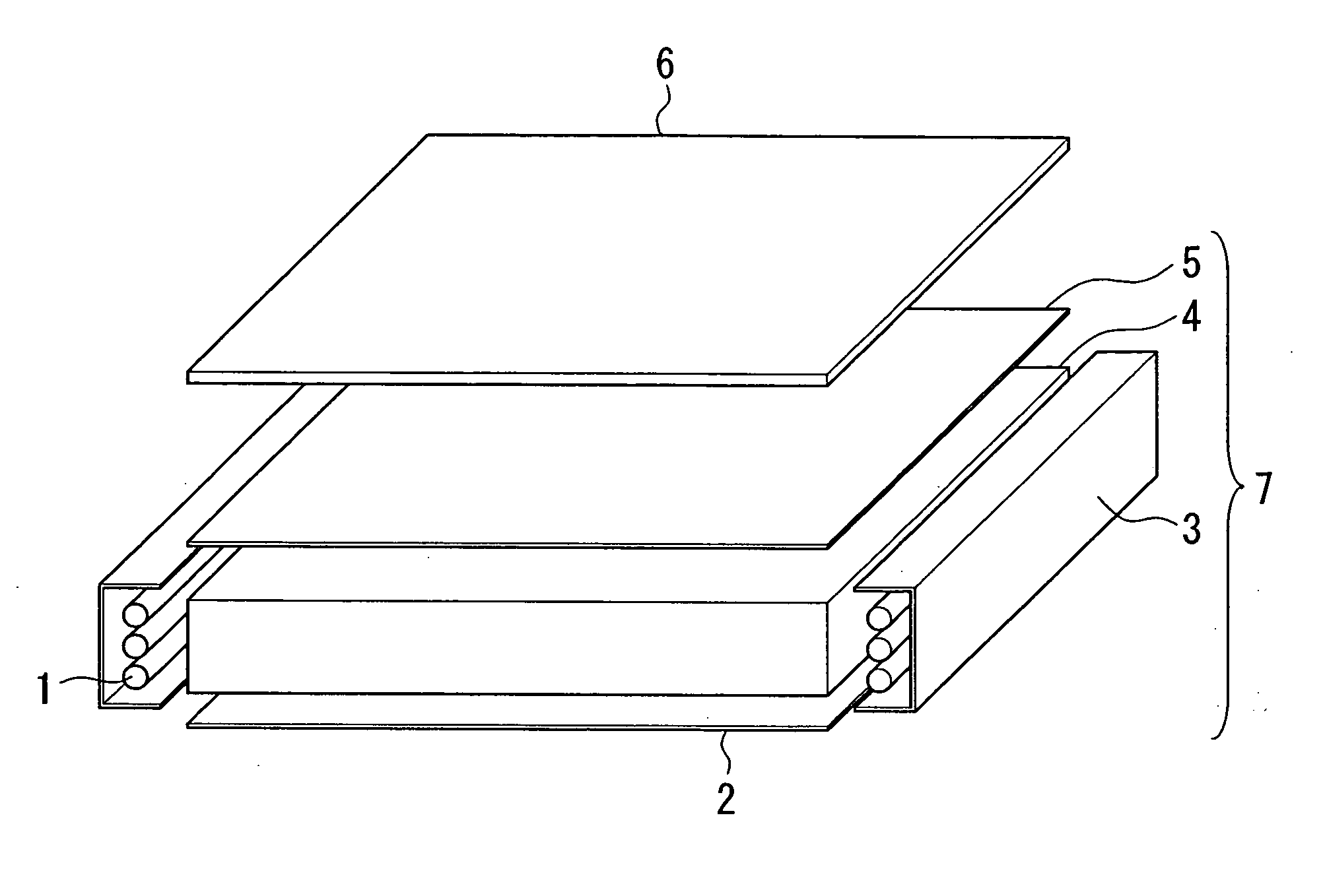
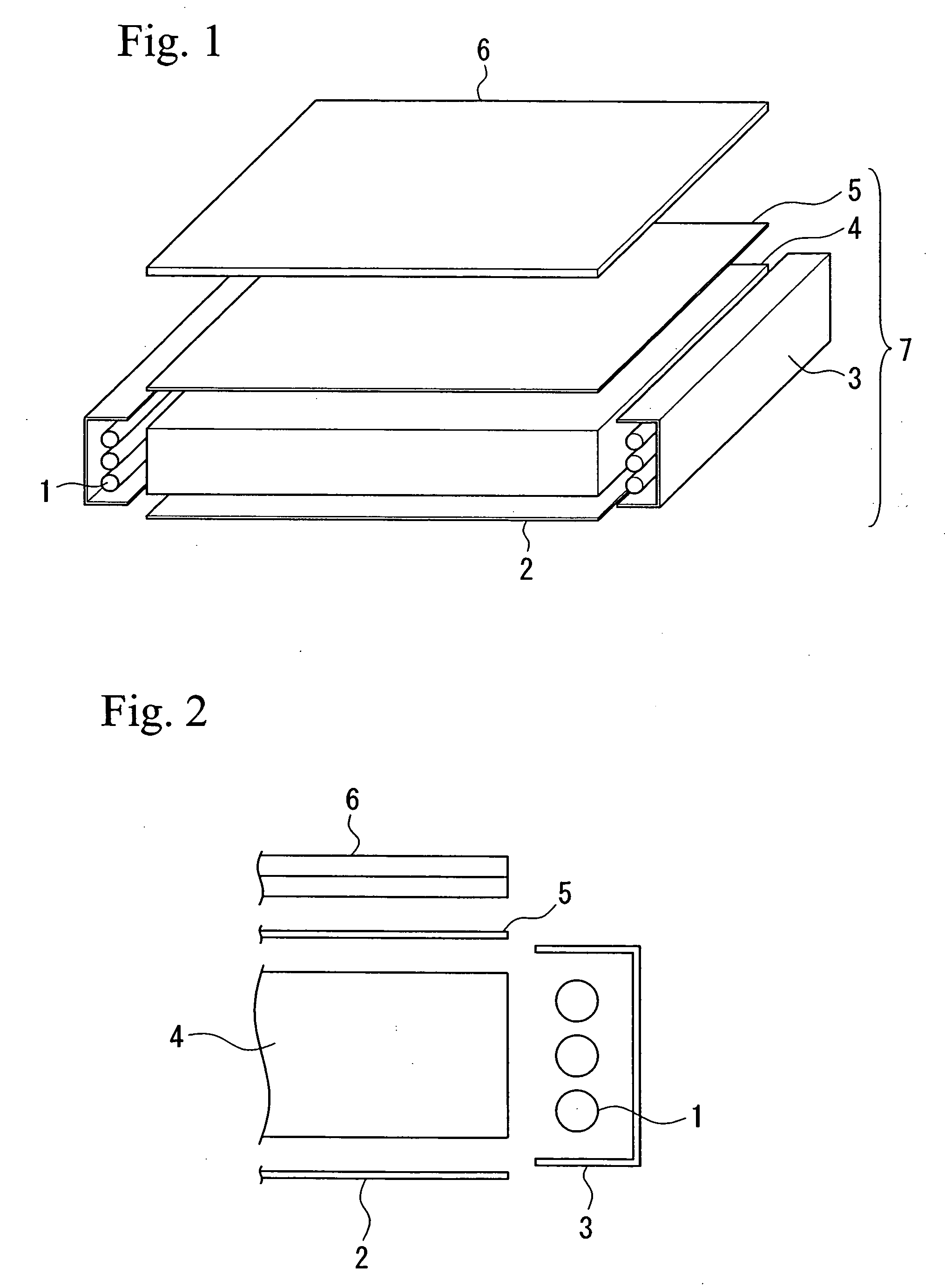
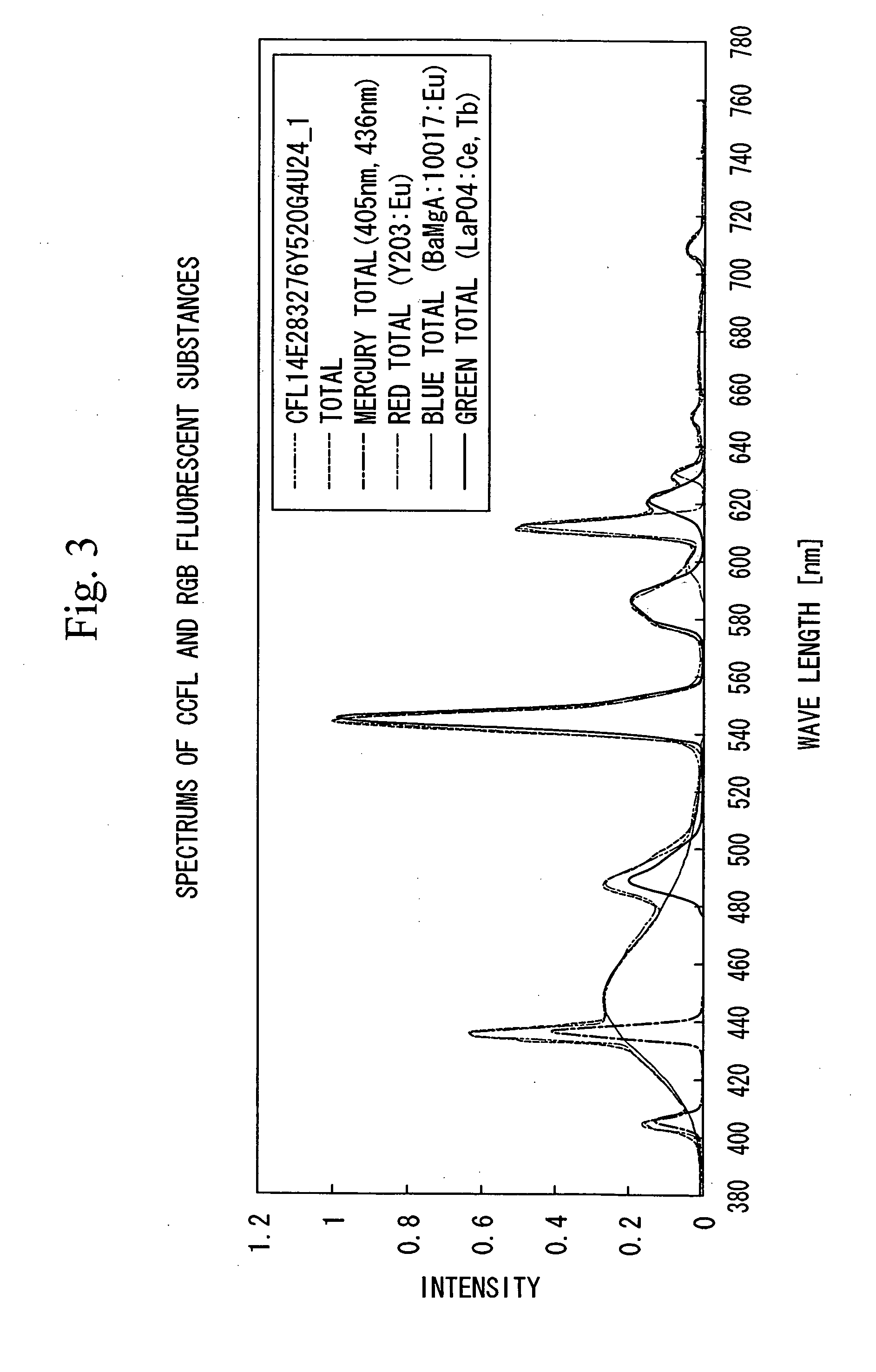
[0048] The first embodiment of the present invention is described with reference of FIG. 1 to FIG. 3. FIG. 1 is a structural view showing principal portions of an image display apparatus that uses a liquid crystal display panel as a display device, as an example of the image display apparatus according to the present invention. FIG. 2 is a view showing an example of the layout of a cold cathode fluorescent lamp serving as a light source. FIG. 3 is a view showing an example of the emission spectrum of a fluorescent lamp.

[0049] As is shown in FIG. 1, this image display apparatus has a liquid crystal display panel 6 and a backlight unit 7, where the liquid crystal panel 6 being placed on the front surface of the backlight unit 7. The backlight unit 7 comprises a fluorescent lamp 1, a reflective plate 2, a reflector 3, an optical guide plate 4, and an optical sheet 5. As is shown in FIG. 2, three fluorescent lamps 1 are placed in parallel with the edge of the optical guide plate inside...

second embodiment

[0056] As is shown in FIG. 5, when fluorescent lamps 1 having three different luminescent colors are used, a uniform color and brightness is obtained in the center portion of the liquid crystal display panel 6, however, in the vicinity of the ends of the optical guide plate 4 near to the fluorescent lamps 1, the distribution of light that is emitted from the three fluorescent lamps and radiated to the liquid crystal display panel 6 from the backlight unit 7 is different from at center portion, that is, in the vicinity of the ends of the optical guide plate 4, the radiation of the light from the fluorescent lamp 1 that is positioned on the nearest side of the reflective plate 2 is abruptly attenuated. Accordingly, in case the luminescent colors of the three fluorescent lamps 1 are different, at end portions of the liquid crystal display panel 6 near the fluorescent lamps 1, coloring unevenness will occur because the color of the light radiated to the liquid crystal display panel 6 ch...

third embodiment

[0058] The human eye has the ability to identify the differences of approximately 0.002 in chromaticity coordinates x and y. In order to reduce coloring unevenness at the display surface, it is effective to make the colors of the three fluorescent lamps 1 close to each other. FIG. 9 and FIG. 10 show the examples using a reddish fluorescent lamp in which phosphor having red and green emission spectrums are mixed with a ratio of (red 5: green 5), a greenish fluorescent lamp in which phosphor having green and blue emission spectrums are mixed with a ratio of (green 8: blue 2), and a bluish fluorescent lamp in which phosphor having red and green and blue emission spectrums are mixed with a ratio of (red 68: green 17: blue 15). The lighting colors of the respective fluorescent lamp are all similar colors, and the color reproduction range is narrow, as is shown in FIG. 9 and FIG. 10. However, it is possible to realize the white colors of P45 and P104 by lighting intensity ratio adjustment...


PUM


Abstract

An image display apparatus is provided that enables the chromaticity of a display screen of a display apparatus to be adjusted to the chromaticity desired by a user. The image display apparatus is formed by a backlight unit that is provided with a plurality of light sources and by an image display panel that is placed at a front surface of the backlight unit. The image display apparatus performs a monochrome display. In the image display apparatus, the light sources have at least three different types of luminescent colors that surround a target color on a chromaticity diagram.

Description

BACKGROUND OF THE INVENTION [0001] 1. Field of the Invention [0002] Priority is claimed on Japanese Patent Application No. 2003-400400, filed Nov. 28, 2003, the contents of which are incorporated herein by reference. [0003] The present invention relates to an image display apparatus for displaying a monochrome image comprising a backlight unit that is provided with a plurality of light sources and an image display panel that is placed in front of the backlight unit. [0004] 2. Description of Related Art [0005] Recent years have seen a rapid change in display apparatuses from those that use CRT as display devices to those that use liquid crystal panels as display devices. The most common display apparatuses that use liquid crystal panels as a display device (hereinafter, referred to as liquid crystal display apparatuses) are those that have light sources on a rear surface of a display panel (i.e., of a liquid crystal panel). Fluorescent lamps are often used for the light sources used ...

Claims


Application Information

Patent Timeline
IPC IPC(8): F21V8/00G02F1/13357F21Y103/00G02F1/133G09F9/35G09G3/00G09G3/20G09G3/34G09G3/36H01J1/62
CPCG09G3/3413G09G2320/043G09G2360/145G09G2320/0666G09G2320/08G09G2320/064G02F1/133
Inventor KOKUBO, HISATOYOSHIOKA, KAZUOITAYA, HIDEKITERAMATSU, HIDEKIYUUKI, AKIMASAODA, KYOICHIRO
Owner MITSUBISHI ELECTRIC CORP
Why Eureka
Try Eureka