
Optical semiconductor lighting apparatus

a technology of optical devices and semiconductors, applied in lighting devices, electrical devices, light sources, etc., can solve the problems of complex design, heat dissipation performance of power units, including electronic devices, etc., and achieve the effect of improving heat dissipation efficiency and stable driving of semiconductor optical devices and circuits

Inactive Publication Date: 2015-05-07
POSCO LED
View PDF2 Cites 6 Cited by
  • Summary
  • Abstract
  • Description
  • Claims
  • Application Information

AI Technical Summary

Benefits of technology

The present invention is a lighting apparatus that uses semiconductor optical devices and circuits. It has improved heat dissipation and stable driving of the devices. It also has a long lifespan and is electrically stable, while reducing weight and costs. Overall, it meets specifications and provides improved performance.

Problems solved by technology

However, such a structure, in which the light-emitting device 100 being the light-emitting unit is separate from the power unit module 200 being the circuit unit, has a problem that a design is complicated and heat dissipation performance of the power unit module 200 including an electronic device 220 such as an SMPS is degraded.
Even in the case of a structure having the light-emitting unit and the circuit unit integrally formed on a single insulation board, as is obvious to those skilled in the art, application of various circuit components inevitably degrades heat dissipation performance due to dense arrangement of such circuit components.
When the light-emitting unit and the circuit unit are integrally formed on a single insulation board as described above, the heat sink needs to have a wide and thick base, in order to prevent degradation of heat dissipation performance, making it impossible to make the light engine lightweight and compact.
In addition, when the light-emitting unit and the circuit unit are separate from each other, or when the light-emitting unit and the circuit unit are integrally formed on an FR4 PCB, an insulation pad is used in either case to electrically insulate between the board and the heat sink, greatly degrading the heat dissipation performance of the circuit unit.
However, such a type of light engine, which includes a light-emitting unit and a circuit integrally formed on a heat-dissipation metal substrate, has a problem in that it cannot meet the requirements of Zhaga that the connector be an insulation board.

Method used


Image

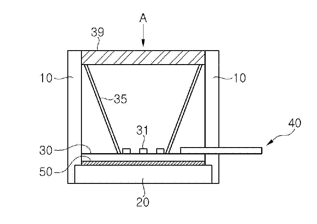
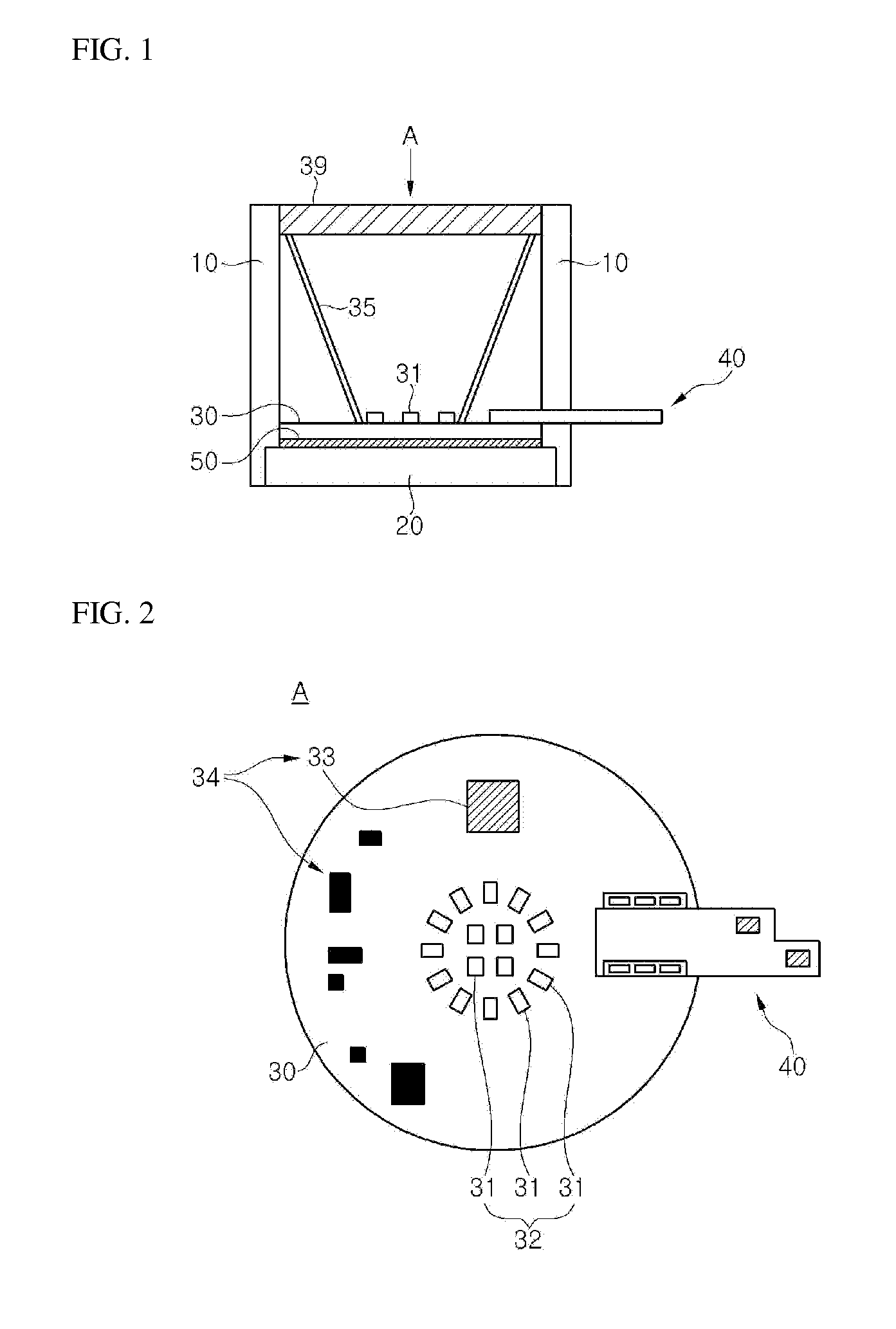
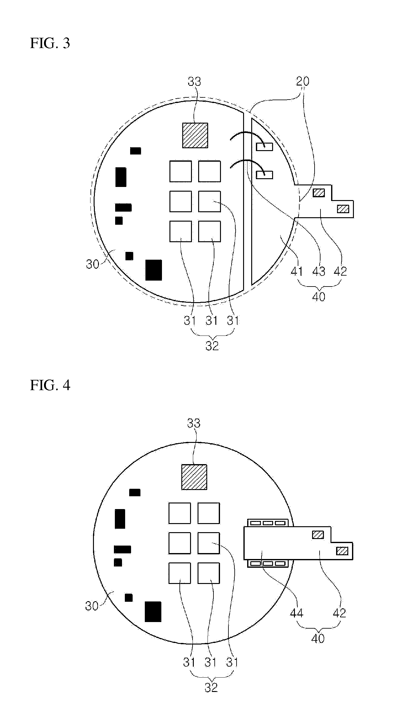
  • Optical semiconductor lighting apparatus
  • Optical semiconductor lighting apparatus
  • Optical semiconductor lighting apparatus

Examples


Embodiment Construction

[0045]The advantages and features of the present invention and methods for achieving them will become more apparent from embodiments to be described below in detail in conjunction with the accompanying drawings.

[0046]However, the present invention is not limited to the embodiments set forth below, and can be implemented in various forms.

[0047]These embodiments are provided so that this disclosure will be thorough and complete, and will fully convey the scope of the present invention to those skilled in the art.

[0048]The scope of the present invention will be defined by only the appended claims.

[0049]Therefore, in some embodiments, detailed descriptions of related known functions or configurations will be omitted if they are considered to unnecessarily obscure the gist of the present invention.

[0050]Throughout the disclosure, like reference numerals refer to like parts throughout the drawings and embodiments of the present invention. The terms used (mentioned) in the present applicat...


PUM


Abstract

An optical semiconductor lighting apparatus includes: a housing; a heat discharge block which is made of a metal and is embedded in the housing; an AC direct-connection module which is made of a metal and is embedded in the housing, the AC direct-connection module including a semiconductor optical device which is driven in an AC direct-connection scheme; and an insulation connector which is provided in the AC direct-connection module and is exposed to an outside of the housing for electrical connection with an external power source.

Description

CROSS REFERENCE TO RELATED APPLICATION[0001]This application claims the benefit of U.S. Provisional Patent Application No. 61 / 901,189, filed on Nov. 7, 2013, which is hereby incorporated by reference for all purposes as if fully set forth herein.BACKGROUND OF THE INVENTION[0002]1. Field of the Invention[0003]The present invention relates to an optical semiconductor lighting apparatus, and more particularly, to an optical semiconductor lighting apparatus including a semiconductor optical device as a light source, which is driven in an AC direct-connection scheme, thereby improving heat dissipation efficiency and obtaining stable driving of the semiconductor optical device and circuits.[0004]2. Description of the Related Art[0005]As compared with incandescent bulbs and fluorescent lamps, optical semiconductors using a light source, such as a light-emitting diode (LED), an organic LED, a laser diode, and an organic electroluminescent diode, have low power consumption, long lifespans, s...

Claims


Application Information

Patent Timeline
Patent Type & Authority Applications(United States)
IPC IPC(8): H05B33/08H05B45/50H05B44/00
CPCH05B33/08H05B45/00H05B45/50
Inventor KIM, KYUNG-RYEKOOK, JI EUNPARK, SEON MIN
Owner POSCO LED
Learn More