
System for Closed Transfer of Fluids With a Locking Member

a technology of fluid transfer and locking member, which is applied in the direction of hose connection, packaging food items, packaged goods type, etc., can solve the problems of nursing cancer patients at risk of exposure, presenting a major hazard in the health care environment, and health care providers at risk of exposur

Active Publication Date: 2015-05-07
BECTON DICKINSON & CO
View PDF32 Cites 82 Cited by
  • Summary
  • Abstract
  • Description
  • Claims
  • Application Information

AI Technical Summary

Benefits of technology

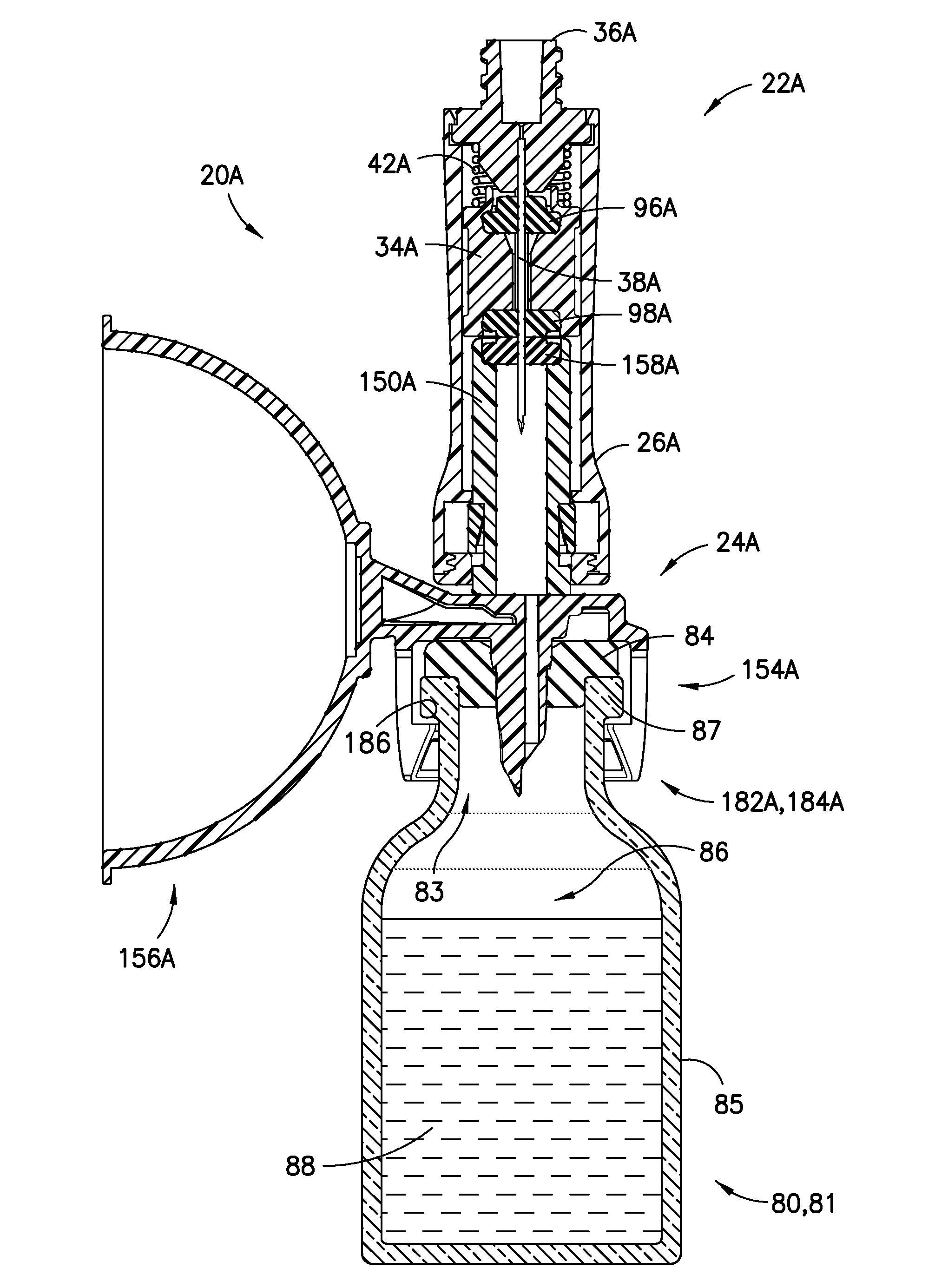
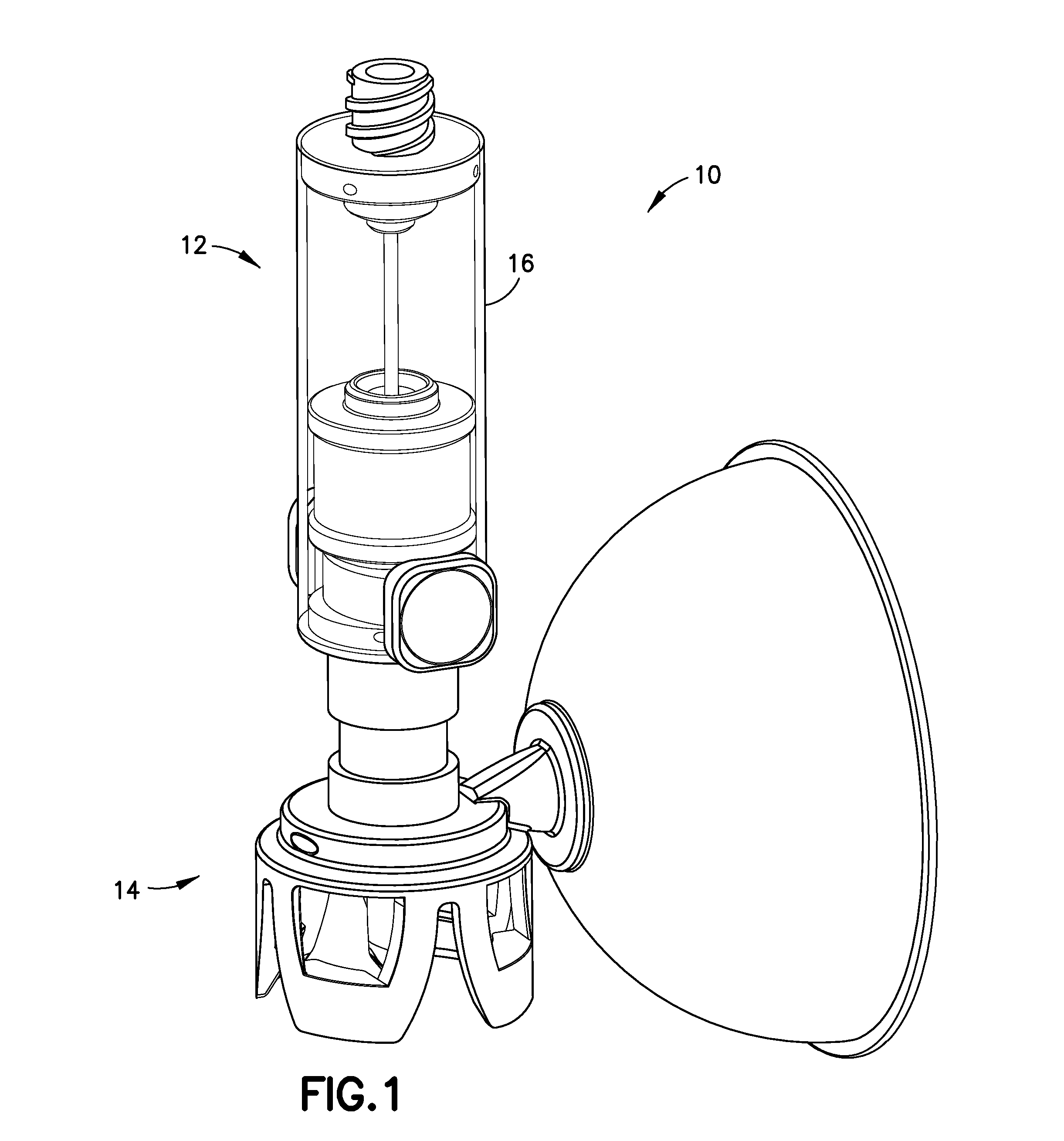
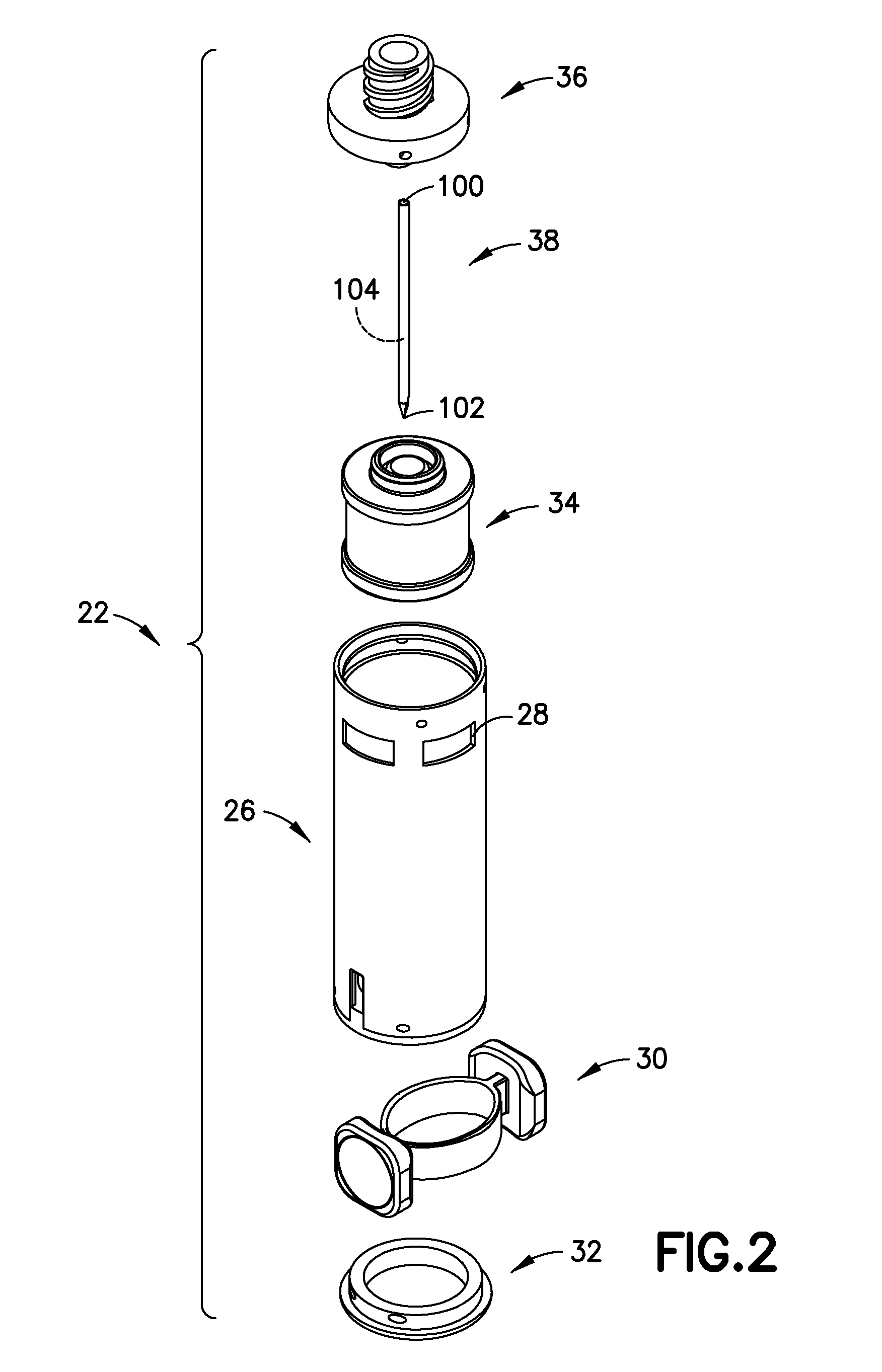
The patent text describes a connector system for a medical device that allows for the transfer of fluids between two devices. The system includes a first connector and a second connector that can be locked together to create a secure connection. The system also includes a locking member that can be transitioned between a locked position and an unlocked position. The locking member is a spring body that is received by the first connector and can be opened and closed to lock the connectors in place. The system can be used with a syringe adapter and a vial access device to transfer fluids between the two devices. The technical effects of this system include improved fluid transfer and secure locking of the connectors.

Problems solved by technology

Health care providers reconstituting, transporting, and administering hazardous drugs, such as cancer treatments, can put health care providers at risk of exposure to these medications and present a major hazard in the health care environment.
For example, nurses treating cancer patients risk being exposed to chemotherapy drugs and their toxic effects.
Unintentional chemotherapy exposure can affect the nervous system, impair the reproductive system, and bring an increased risk of developing blood cancers in the future.

Method used


Image

  • System for Closed Transfer of Fluids With a Locking Member
  • System for Closed Transfer of Fluids With a Locking Member
  • System for Closed Transfer of Fluids With a Locking Member

Examples


Embodiment Construction

[0107]The following description is provided to enable those skilled in the art to make and use the described aspects contemplated for carrying out the invention. Various modifications, equivalents, variations, and alternatives, however, will remain readily apparent to those skilled in the art. Any and all such modifications, variations, equivalents, and alternatives are intended to fall within the spirit and scope of the present invention.

[0108]For purposes of the description hereinafter, the terms “upper”, “lower”, “right”, “left”, “vertical”, “horizontal”, “top”, “bottom”, “lateral”, “longitudinal”, and derivatives thereof shall relate to the invention as it is oriented in the drawing figures. However, it is to be understood that the invention may assume various alternative variations, except where expressly specified to the contrary. It is also to be understood that the specific devices illustrated in the attached drawings, and described in the following specification, are simply...


PUM


Abstract

A connector system for a medical device includes a first connector having an elongate opening, and a second connector including a lock portion, where the first connector is movable relative to the second connector between an initial position where the first connector is not in fluid communication with the second connector and an activated position where the first connector is in fluid communication with the second connector. The system also includes a locking member connected to the first connector. The locking member is transitionable between an unlocked position where the second connector is movable within the elongate opening of the first connector and a locked position where the locking member is configured to engage the lock portion of the second connector to lock the first connector to the second connector in the activated position. The locking member comprises a spring body received by the elongate opening of the first connector.

Description

CROSS-REFERENCE TO RELATED APPLICATION[0001]This application claims priority to U.S. Provisional Application Ser. No. 61 / 900,674, filed Nov. 6, 2013, which is hereby incorporated by reference in its entirety.BACKGROUND OF THE INVENTION[0002]1. Field of the Disclosure[0003]The present disclosure relates generally to a system for the closed transfer of fluids. More particularly, the present disclosure relates to a system that provides leak-proof sealing and pressure equalization during engagement of a cannula with a vial, during transfer of a substance from a vial chamber to a barrel chamber via the cannula, and during disengagement of the cannula from the vial.[0004]2. Description of the Related Art[0005]Health care providers reconstituting, transporting, and administering hazardous drugs, such as cancer treatments, can put health care providers at risk of exposure to these medications and present a major hazard in the health care environment. For example, nurses treating cancer pati...

Claims


Application Information

Patent Timeline
Patent Type & Authority Applications(United States)
IPC IPC(8): A61J1/20A61M39/10
CPCA61J1/2096A61J2200/70A61M39/1011A61M2039/1027A61J1/2055A61J1/1406A61J1/2089A61J1/201A61J1/2075A61J1/1481A61J1/2058Y10S604/905Y10S285/921A61M2039/1016F16L37/084F16L37/0841F16L37/142F16L37/144
Inventor SANDERS, LAURIEYEVMENENKO, YAN
Owner BECTON DICKINSON & CO
Learn More