
Method of Device Attachment to a Biological Surface

Active Publication Date: 2015-04-30
ARKIS BIOSCI
View PDF7 Cites 5 Cited by
  • Summary
  • Abstract
  • Description
  • Claims
  • Application Information

AI Technical Summary

Benefits of technology

The patent describes a device and method for securely attaching an implantable drainage lumen, catheter, or other device to an internal bodily surface, such as the peritoneum. The device includes a mesh fabric that is connected to the implantable device and can be surgically affixed to the tissue or organ. The mesh fabric can be made of a biocompatible material, such as collagen or polyester, and can have a porous or perforated surface to facilitate tissue growth and biological attachment. The attachment can be made through a mechanical, electrical, or biological growth process, and temporary fixture devices can be used to hold the mesh in place. The technical effect of this invention is to provide a secure and effective means for attaching implantable devices to the body.

Problems solved by technology

Movement generated by the patient, or by other biological functions, can cause undesirable internal migration of the drainage system which can result in a disruption of either the collection or discharge of CSF and thereby a non-optimal reabsorption of CSF by the shunt system.
Furthermore, migration of the shunt's drainage lumen(s) may interfere with other bodily functions for example in the case where drainage tubing may wrap around internal organs such as the intestines.

Method used


Image

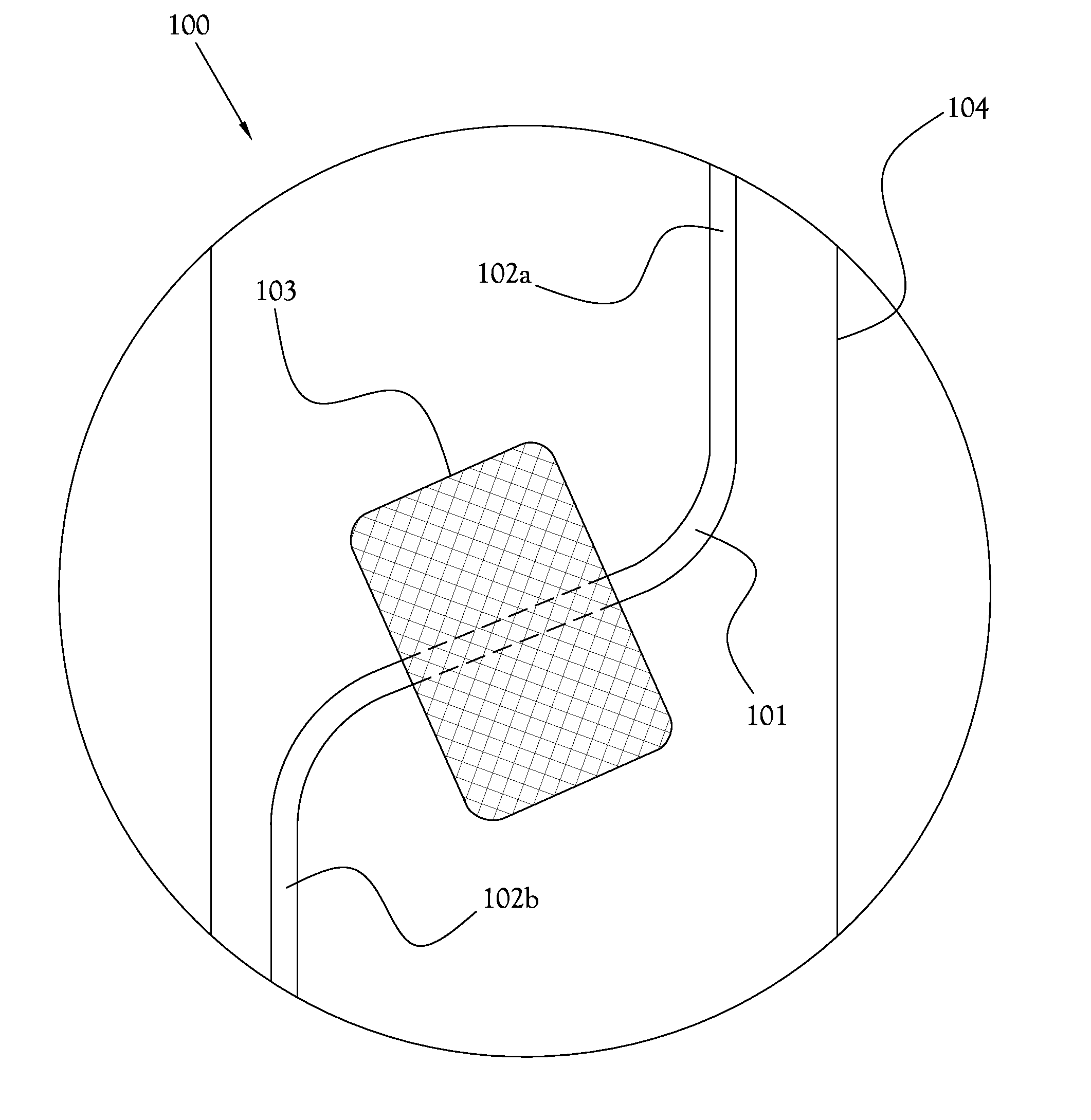
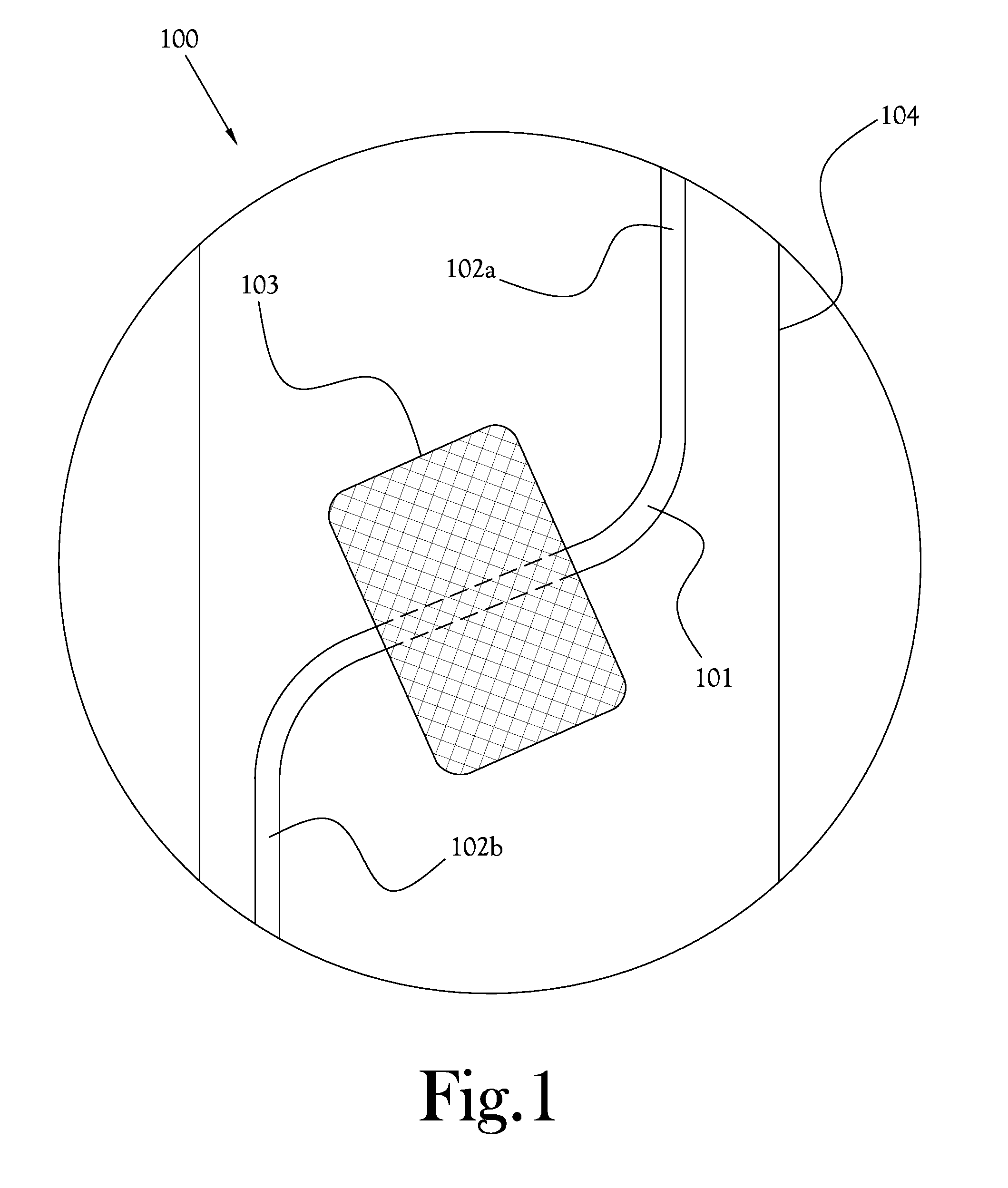
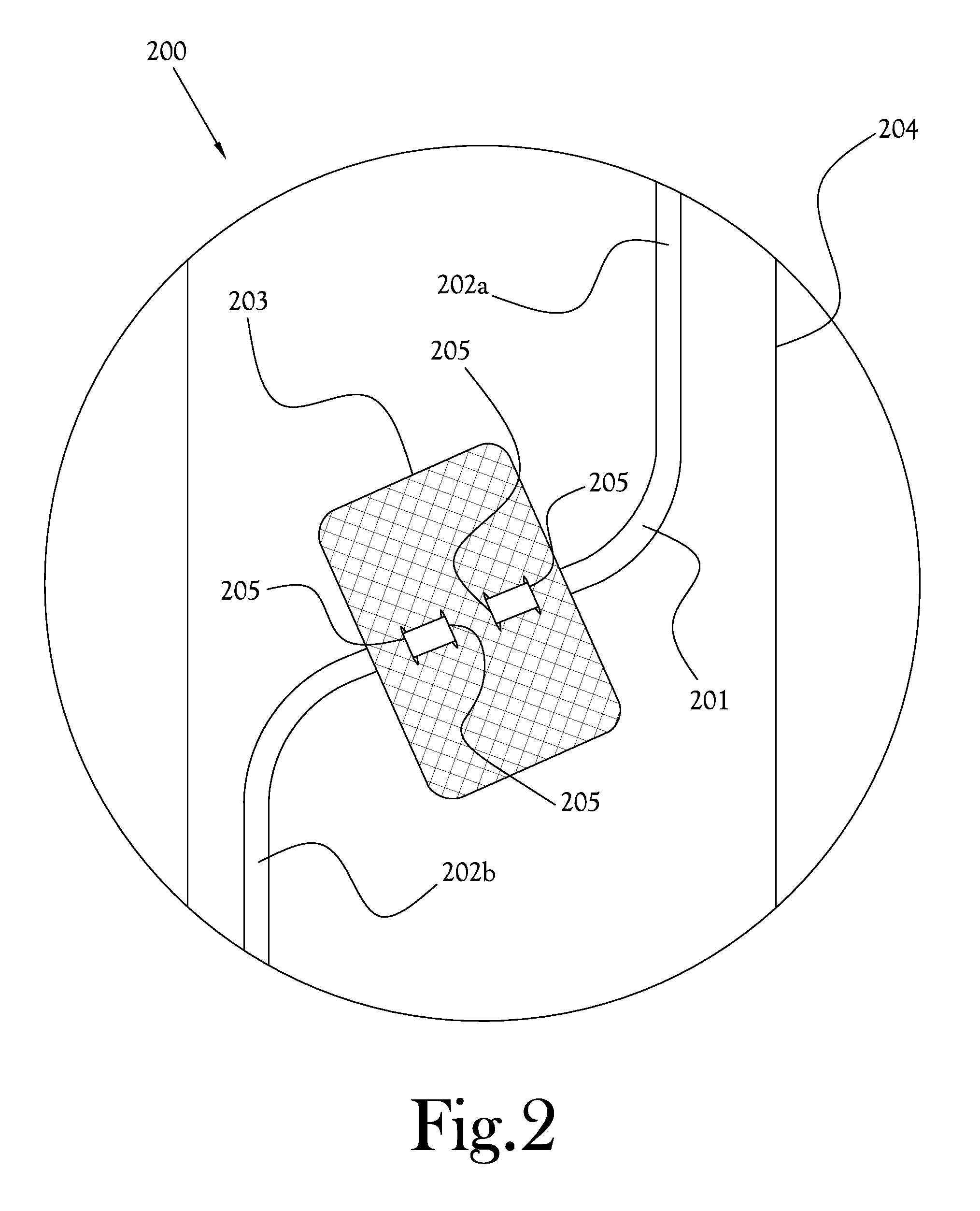
  • Method of Device Attachment to a Biological Surface
  • Method of Device Attachment to a Biological Surface
  • Method of Device Attachment to a Biological Surface

Examples


Embodiment Construction

[0043]Reference will now be made to example embodiments of the present general inventive concept, examples of which are illustrated in the accompanying drawings and illustrations. The example embodiments are described herein in order to explain the present general inventive concept by referring to the figures.

[0044]Note that spatially relative terms, such as “up,”“down,”“right,”“left,”“beneath,”“below,”“lower,”“above,”“upper” and the like, may be used herein for ease of description to describe one element or feature's relationship to another element(s) or feature(s) as illustrated in the figures. Spatially relative terms are intended to encompass different orientations of the device in use or operation in addition to the orientation depicted in the figures. For example, if the device in the figures is turned over or rotated, elements described as “below” or “beneath” other elements or features would then be oriented “above” the other elements or features. Thus, the exemplary term “b...


PUM


Abstract

A device and means of attaching an implantable drainage lumen, catheter, or other device to an internal bodily surface, such as the peritoneum, is generally indicated by a biocompatible material or mesh fabric connected to a lumen, catheter, or other mechanical or electrical device whereby the biocompatible material or mesh may be surgically affixed to a tissue or organ by means of sutures, tacks, screws, tissue infusion or adhesion or other means in order to secure an internal drainage, or mechanical / electrical system or component for the prevention of migration or non-optimal CSF reabsorption after installation.

Description

CROSS-REFERENCE TO RELATED APPLICATIONS[0001]This Application claims the benefit of U.S. Provisional Patent Application Ser. No. 61 / 896,020, filed Oct. 25, 2013, the contents of which are incorporated herein by reference in its entirety.BACKGROUND OF THE INVENTION[0002]1. Field of Invention[0003]The present general inventive concept relates to systems and methods of treating hydrocephalus or the like, and more particularly, to ventricular or lumbar cerebral spinal fluid (CSF) shunt systems.[0004]2. Description of the Related Art[0005]A common contemporary treatment of hydrocephalus is to divert the flow of CSF. One strategy in obstructive hydrocephalus is to surgically pierce a hole in the bottom of the third ventricle, bypassing the obstruction. However, most commonly, CSF is diverted to a space in the body that has a large capacity to absorb it such as the peritoneum, pleura, or bloodstream. This strategy can be used with obstructive or communicating hydrocephalus and is accomplis...

Claims


Application Information

Patent Timeline
IPC IPC(8): A61M27/00
CPCA61M2209/08A61M27/006A61M25/04A61M2025/0286
Inventor KILLEFFER, JAMES ALEXANDERSEAVER, CHAD ERICTAYLOR, DANA A.ARNOTT, JAMES CHRISTOPHER
Owner ARKIS BIOSCI
Learn More