Transformer and high voltage power supply apparatus having the same

a transformer and high voltage technology, applied in the field of transformers, can solve the problems of shortening the durability of the transformer, vibration of the transformer, and the inability to obtain the required second voltage, and achieve the effect of reducing the spa

Active Publication Date: 2015-04-30
KOREA ELECTROTECH RES INST
View PDF7 Cites 3 Cited by
  • Summary
  • Abstract
  • Description
  • Claims
  • Application Information

AI Technical Summary

Benefits of technology

The present invention provides a transformer and high voltage power supply apparatus that have several advantages. First, it allows for more turns in the second coil unit without needing layer insulation, which is common in conventional winding methods. Second, it allows for better surface discharge between the first and second coil units. Third, it allows for proper insulation between the second coil units and a compact arrangement in a system with multiple transformers, reducing space requirements.

Problems solved by technology

And the saturation phenomenon induces a harmonic frequency which shortens the durability of the transformer or cause vibration of the transformer.
In addition, the saturated transformer loses the function as a transformer; thereby the required second voltage cannot be obtained.
But this method has a problem that the volume of the transformer and the manufacturing cost increase.
But when the coil in the second coil unit is wound on the bobbin 130 by this method, the longitudinal center of the high voltage transformer has a convex shape, which results in increase in volume of the transformer and makes maintenance of a proper distance from the second coil unit of the adjacent transformer impossible.
In addition, there is a problem that the turns in the second coil unit are limited when the height of the coil layers becomes higher, and then efficiency falls.
In particular, when the second coil unit wound in the core of EE shape or UU shape, the distance between the second coils wound on both sides decreases, thereby insulation destruction phenomenon may occur.

Method used


Image

  • Transformer and high voltage power supply apparatus having the same
  • Transformer and high voltage power supply apparatus having the same
  • Transformer and high voltage power supply apparatus having the same

Examples


Embodiment Construction

[0082]Hereinafter, preferred embodiments of the present invention will be explained in more detail with reference to the attached drawings.

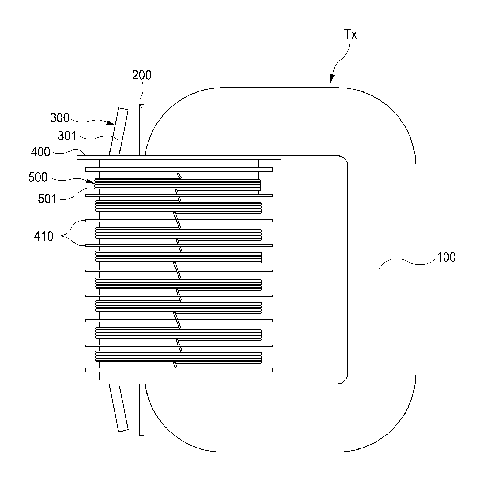
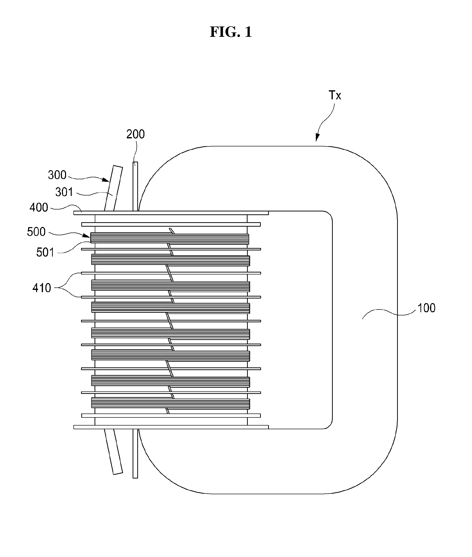
[0083]FIG. 1 is a side view showing the transformer in accordance with the embodiment of the present invention, and FIG. 2 is a perspective view showing the transformer in accordance with the embodiment of the present invention.

[0084]The transformer in accordance with the embodiment of the present invention may include a core 100, an insulating body 200, first coil unit 300, bobbin 400 and a second coil unit 500.

[0085]The core 100 of the transformer Tx in accordance with the embodiment of the present invention may have a rectangular shape, and a hole may be formed within the core. And iron core or ferrite may be selected as the material of this core 100, but not limited to this; any other material in which magnetic flux may smoothly flow may be used as an alternative.

[0086]The first coil 300 may be wound on only one side of the four sides of the ...


PUM


Abstract

A transformer including first coil unit and second unit, wherein one or more coils are wound on the bobbin of insulating material in at least one of the first coil unit and the second unit, and wherein the bobbin is formed with at least one partitioning flange for partitioning a coil winding surface of the bobbin into two winding surfaces along the longitudinal direction of the bobbin, is disclosed.

Description

BACKGROUND OF THE INVENTION[0001]1. Technical Field[0002]The present invention relates to a transformer, more particularly to a high voltage transformer and a high voltage power supply apparatus having the same.[0003]2. Description of the Related Art[0004]A transformer is an apparatus for changing voltage value or current value of AC (Alternating Current) by using electromagnetic phenomenon.[0005]In case that the voltage is raised by using the transformer, particularly a DC / DC converter, the transformer may be saturated by the operating frequency and the voltage applied to the first coils.[0006]The saturation of the transformer is a phenomenon that if the magnetic flux density is over the specific value, the magnetic flux density rarely increase despite the increase of the magnetizing force although the magnetic flux density generally increases when the magnetizing force increase. And the saturation phenomenon induces a harmonic frequency which shortens the durability of the transfo...

Claims


Application Information

Patent Timeline
IPC IPC(8): H02M3/335H01F27/28
CPCH02M3/33507H01F27/2895H01F27/2823H01F27/325H01F38/42H01F2005/022H02M3/3353H02M1/0077
Inventor RYOO, HONG JEJANG, SUNG ROCKIM, HYOUNGSUKKIM, JONG SOO
Owner KOREA ELECTROTECH RES INST
Why Eureka
Try Eureka