
Objective Allocation of Implant Electrode Bands Based on Excitation Spread

a cochlea implant and electrode array technology, applied in the direction of internal electrodes, artificial respiration, therapy, etc., can solve the problems of spectral and temporal confusion, surgical insertion procedure bears a significant risk of “fold-over” of the electrode array within the cochlea, and the determination of place pitch using a psychoacoustic procedure is very time-consuming and laborious

Active Publication Date: 2015-04-23
MED EL ELEKTROMEDIZINISCHE GERAETE GMBH
View PDF3 Cites 32 Cited by
  • Summary
  • Abstract
  • Description
  • Claims
  • Application Information

AI Technical Summary

Benefits of technology

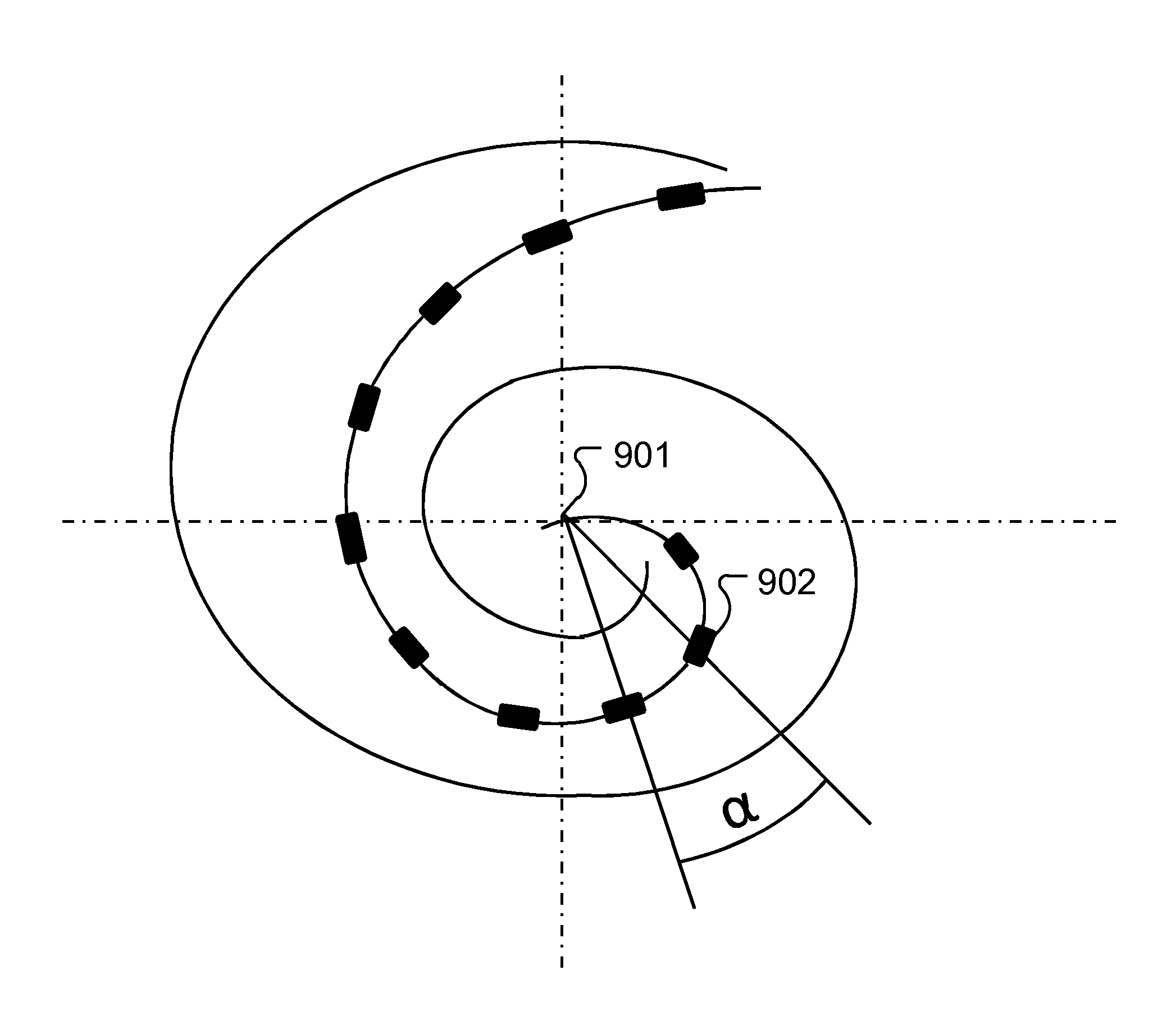
The present invention is about detecting the location of a fold-over in a cochlear implant electrode. This is done by measuring the electrical activity of the electrodes and calculating the current spread for each electrode contact. This information helps to determine the position of the fold-over, which can affect the overall performance of the cochlear implant. The invention also includes a novel arrangement for creating sound perception in an implanted patient, where the electrode array is designed to fold back against the basal section when inserted into the cochlea. Overall, the invention focuses on optimizing the stimulation patterns for cochlear implants to improve their efficiency and accuracy.

Problems solved by technology

One neglected aspect in cochlear implant (CI) fittings is optimization of the frequency-band allocation of each electrode channel since the determination of place pitch using a psychoacoustic procedure is very time consuming.
If these electrode channels present different frequency-band signals to the same neurons, spectral- and temporal-confusion can result.
But the high flexibility of the electrode array means that the surgical insertion procedure bears a significant risk of “fold-overs” of the electrode array within the cochlea.
Such a complex and costly procedure is necessary because other measures such as eCAPs do not allow for distinguishing between a region where the neuronal nerve does not respond and situations where an electrode fold-over occurred; the measurement results do not allow any criteria to be established to differentiate between the two cases.

Method used


Image

  • Objective Allocation of Implant Electrode Bands Based on Excitation Spread
  • Objective Allocation of Implant Electrode Bands Based on Excitation Spread
  • Objective Allocation of Implant Electrode Bands Based on Excitation Spread

Examples


Embodiment Construction

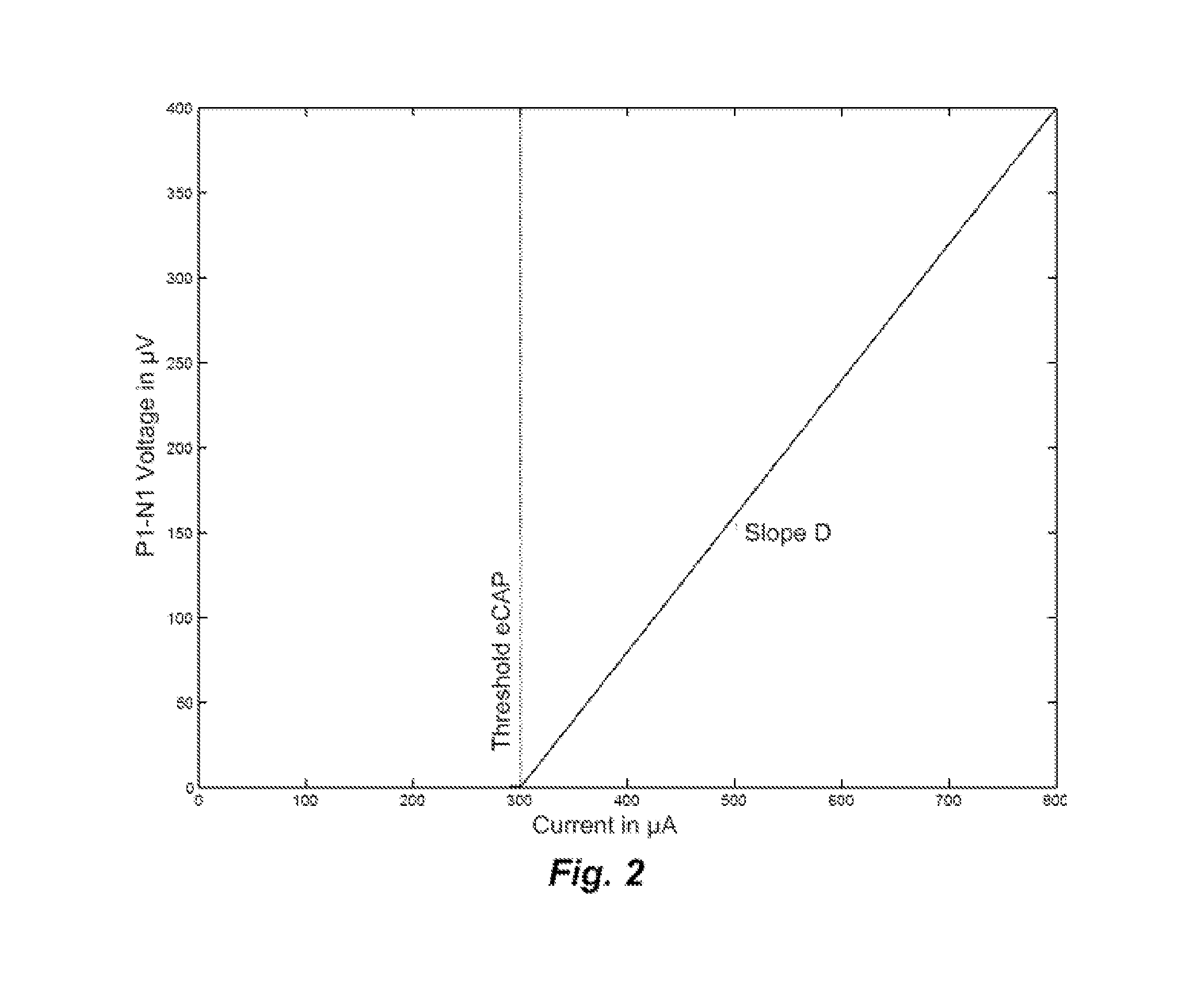
[0025]Embodiments of the present invention are directed to using current spread at the electrode contacts to detect fold-over of the electrode array and subsequent adaptation during stimulation. Once a fold-over is detected, a mapping can be made of the electrode contacts to the various frequency channels and from this an optimal frequency band allocation to each electrode contact. The current spread can be calculated in various ways such as by neural excitation spatial spread (SS) voltage measurements and eCAP (electrically-evoked compound action potentials) threshold measurements or by Impedance Field Telemetry (IFT). One specific embodiment detects electrode array fold-over starting with performing eCAP measurements and determining the amplitude growth function and the eCAP threshold. In spatial current spread SS measurements, a constant stimulus current is used for each electrode contact. This allows an estimation of current spread based on measured SS voltages where for any mis...


PUM


Abstract

A cochlear implant arrangement is described for creating sound perception in an implanted patient. An implant electrode contains electrode wires for carrying stimulation signals to corresponding electrode contacts distributed along a length of an outer surface of an apical electrode array section of the implant electrode. An apical portion of the electrode array is characterized by a tendency to fold back against a more basal section of the electrode array when inserted into a cochlea of the patient. An implantable stimulation processor produces the stimulation signals such that each electrode contact, including any in a folded back portion, delivers stimulation signals for a frequency band defined based on a function of spatial spread of stimulation voltage and correctly associated with tonotopic frequency response of the adjacent neural tissue.

Description

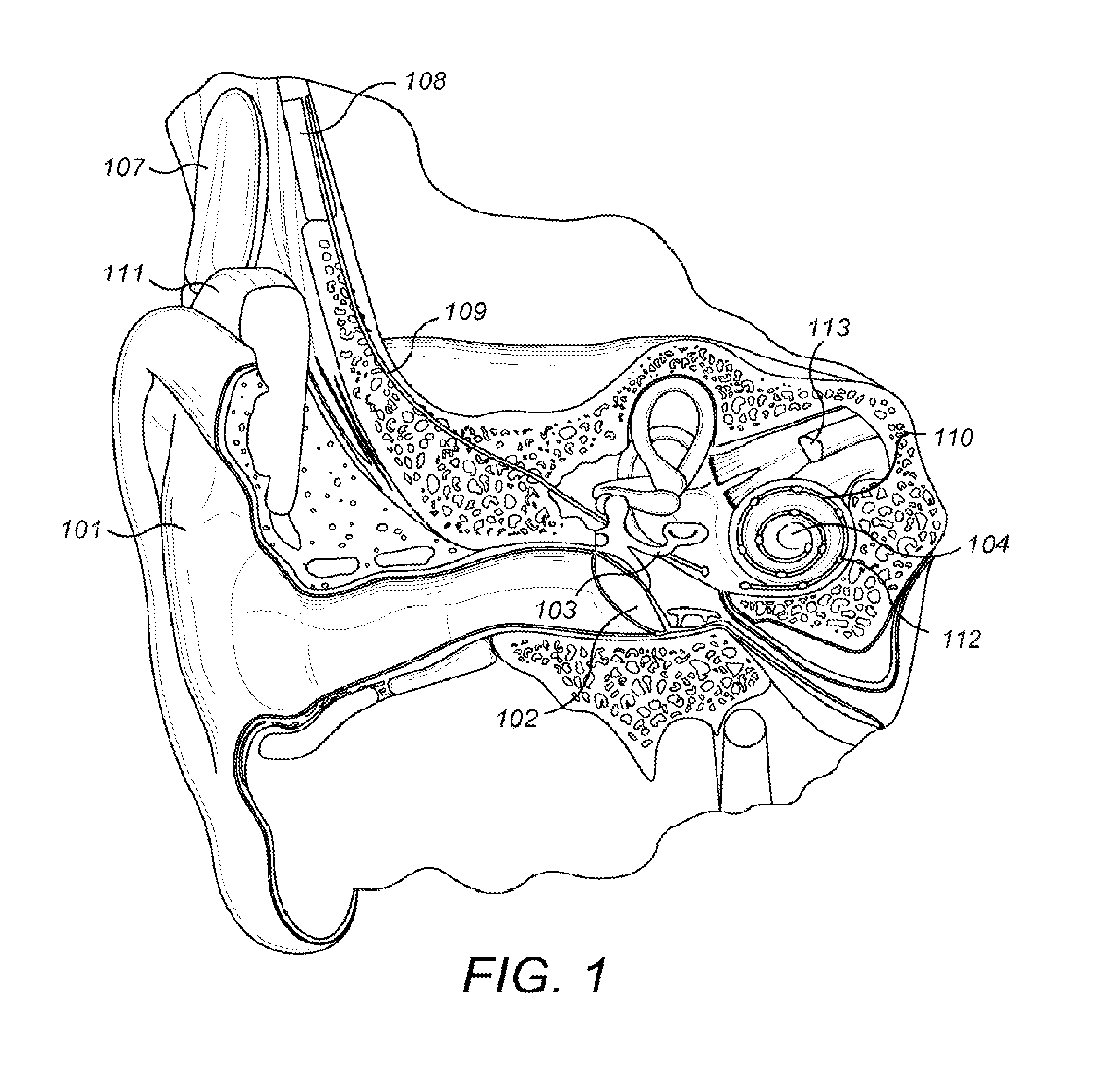
[0001]This application claims priority from U.S. Provisional Patent Application 61 / 891,930, filed Oct. 17, 2013, which is incorporated herein by reference in its entirety.FIELD OF THE INVENTION[0002]The present invention relates to coding stimulation pulses for cochlear implant systems.BACKGROUND ART[0003]A normal ear transmits sounds as shown in FIG. 1 through the outer ear 101 to the tympanic membrane (eardrum) 102, which moves the bones of the middle ear 103 (malleus, incus, and stapes) that vibrate the oval window and round window openings of the cochlea 104. The cochlea 104 is a long narrow duct wound spirally about its axis for approximately two and a half turns. It includes an upper channel known as the scala vestibuli and a lower channel known as the scala tympani, which are connected by the cochlear duct. The cochlea 104 forms an upright spiraling cone with a center called the modiolar where the spiral ganglion cells of the acoustic nerve 113 reside. In response to received...

Claims


Application Information

Patent Timeline
IPC IPC(8): A61N1/05A61N1/08A61N1/36
CPCA61N1/0541A61N2001/083A61N1/08A61N1/36032A61N1/36038A61N1/36039
Inventor KALS, MATHIAS
Owner MED EL ELEKTROMEDIZINISCHE GERAETE GMBH
Learn More