
Universal Cranioplasty Mesh

a mesh and cranioplasty technology, applied in the field of surgery, can solve the problems of loss of countersunk fittings around the edges, time-consuming and technically demanding to bend the mesh to the desired configuration, and difficulty in bending the mesh

Inactive Publication Date: 2015-04-16
DORAFSHR AMIR HOSSEIN +3
View PDF4 Cites 10 Cited by
  • Summary
  • Abstract
  • Description
  • Claims
  • Application Information

AI Technical Summary

Benefits of technology

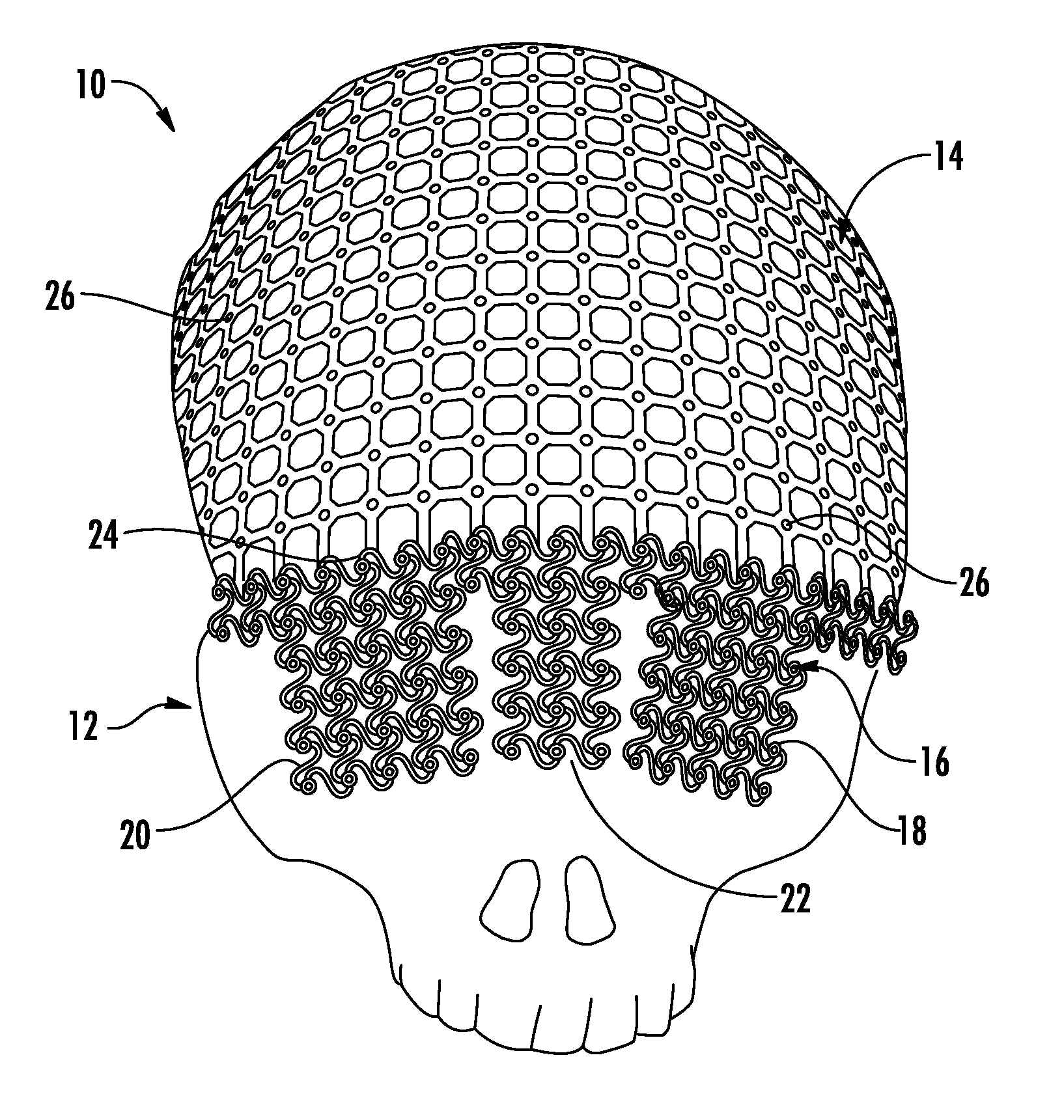
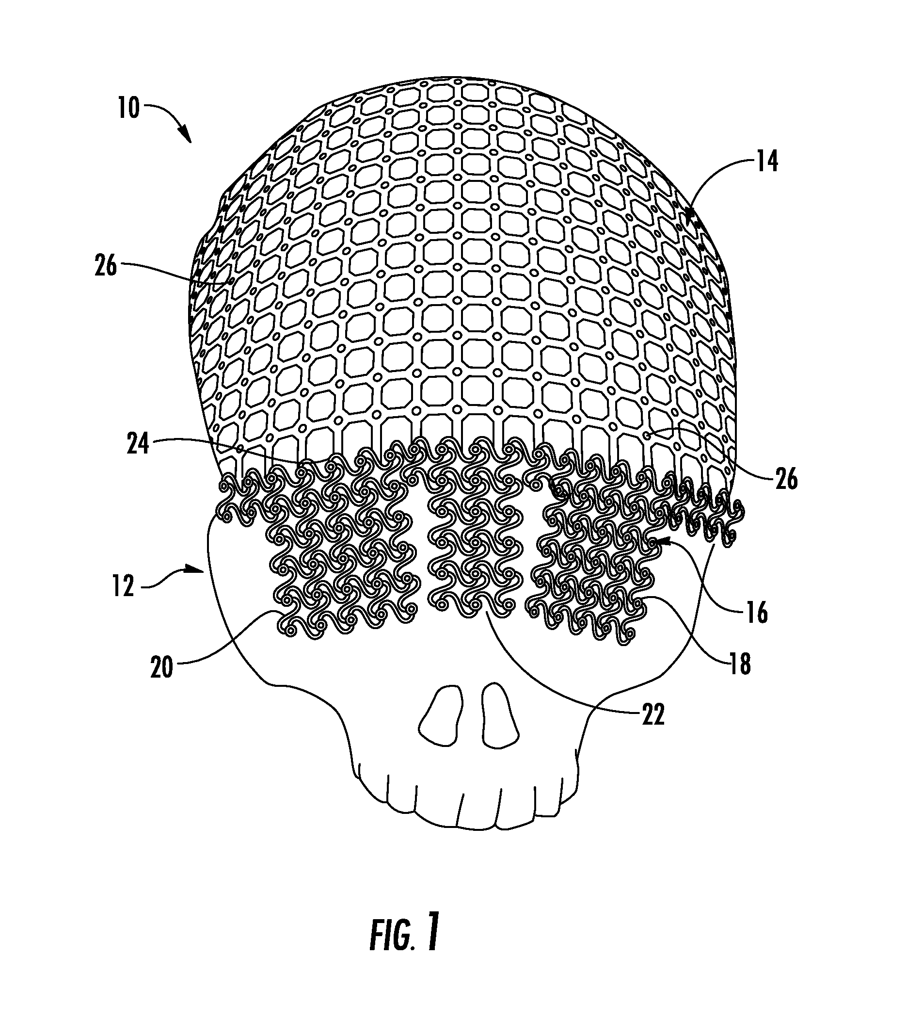
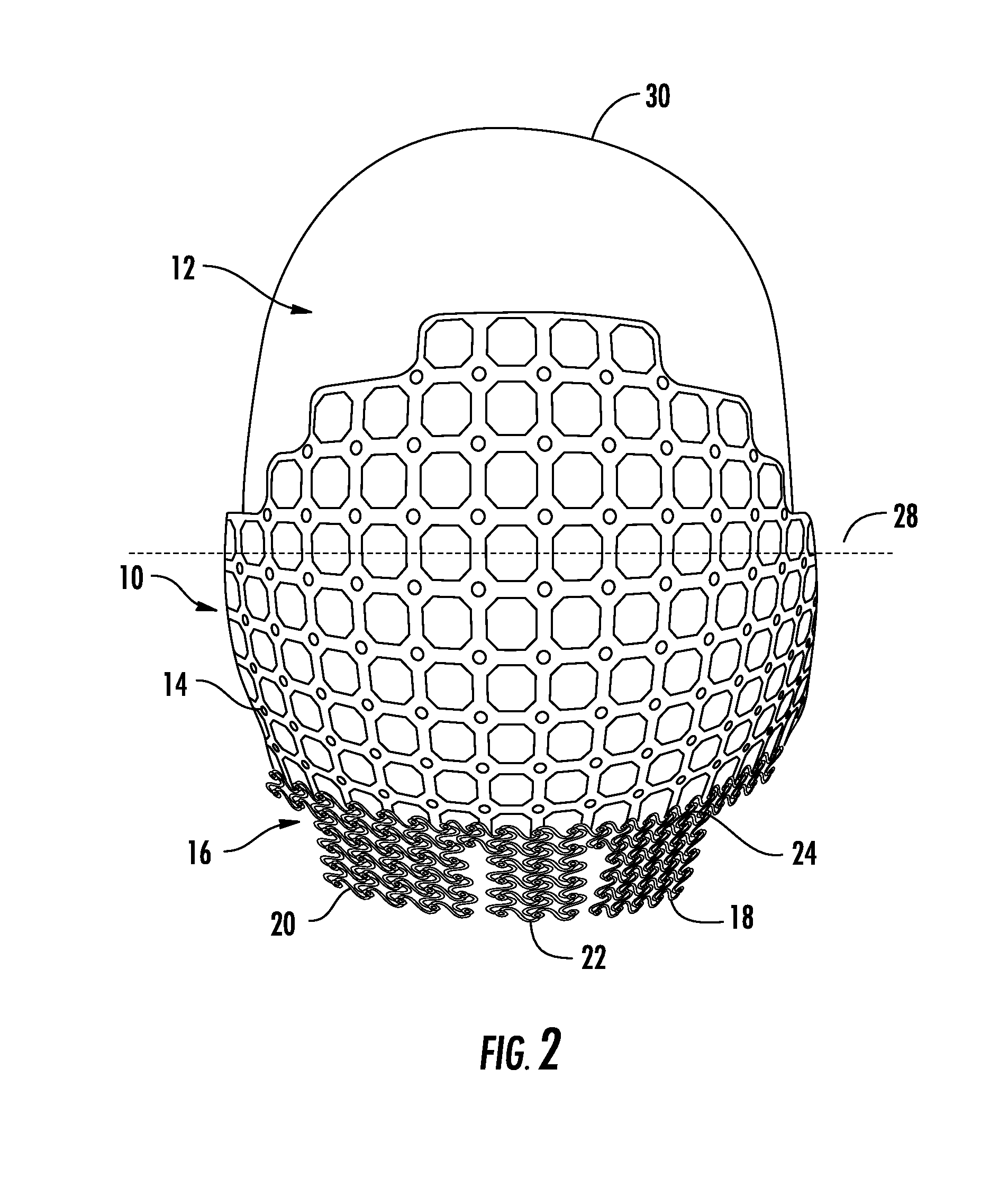
The present invention provides a device and system for cranioplasty that includes a first mesh with a fixed shape and a second mesh with a malleable shape. The two meshes are seamlessly integrated into a hybrid mesh, which allows for better adaptation to the skull. The device also includes a fastener for securing the mesh to the skull. The cranioplasty component can have multiple components that can cover different regions of the skull and can be pre-connected or coupled using a fastener. The first mesh is made of titanium and is pre-formed to match the shape of the skull. The system includes a cranioplasty component and a fastener that provide better protection and aesthetic appearance while also allowing for customization and flexibility during cranioplasty procedures.

Problems solved by technology

However, in some cases, these flat meshes can be hard to bend and do not necessarily remain in the bent position.
Additionally, it can be time consuming and technically demanding to bend the mesh to the desired configuration.
Unfortunately, that means that some areas of the skull are not represented in these pre-formed pieces, especially with respect to pieces that can be used to reconstruct the orbital roof, the nose, the occipital portion of the skull, and the temporal region.
However, if these pre-formed pieces are then cut down to cover a smaller region of the skull, these countersunk fittings around the edges are lost.
This solution can, however, be time consuming to produce and quite costly given the custom nature of the implant.
Additionally, this is not necessarily a viable solution for a trauma situation, in which time is of the essence.

Method used


Image

  • Universal Cranioplasty Mesh
  • Universal Cranioplasty Mesh
  • Universal Cranioplasty Mesh

Examples


Embodiment Construction

[0020]The presently disclosed subject matter now will be described more fully hereinafter with reference to the accompanying Drawings, in which some, but not all embodiments of the inventions are shown. Like numbers refer to like elements throughout. The presently disclosed subject matter may be embodied in many different forms and should not be construed as limited to the embodiments set forth herein; rather, these embodiments are provided so that this disclosure will satisfy applicable legal requirements. Indeed, many modifications and other embodiments of the presently disclosed subject matter set forth herein will come to mind to one skilled in the art to which the presently disclosed subject matter pertains having the benefit of the teachings presented in the foregoing descriptions and the associated Drawings. Therefore, it is to be understood that the presently disclosed subject matter is not to be limited to the specific embodiments disclosed and that modifications and other ...


PUM


Abstract

An embodiment in accordance with the present invention provides a device for use in a cranioplasty including a first mesh, wherein a structure of the first mesh has a generally rigid, contoured configuration. The device also includes a second mesh, wherein a structure of the second mesh has a generally malleable, contoured configuration. The first mesh and the second mesh are also seamlessly integrated into a hybrid mesh. This design allows for rigid structure in certain regions of the implant and customization and malleability in other regions.

Description

CROSS REFERENCE TO RELATED APPLICATIONS[0001]This application claims the benefit of U.S. Provisional Patent Application No. 61 / 621,609 filed on Apr. 9, 2012, which is incorporated by reference, herein, in its entirety.FIELD OF THE INVENTION[0002]The present invention relates generally to surgery. More particularly, the present invention relates to a device for performing a cranioplasty.BACKGROUND OF THE INVENTION[0003]Cranioplasty is a surgical procedure to repair a defect or deformity of a skull. Different methods of performing cranioplasty can be used, such as bone graft, plastic implants, and metal implants.[0004]One type of metal implant used is a flat titanium mesh. This mesh can be bent somewhat to follow the shape of the skull. However, in some cases, these flat meshes can be hard to bend and do not necessarily remain in the bent position. Additionally, it can be time consuming and technically demanding to bend the mesh to the desired configuration.[0005]In order to provide a...

Claims


Application Information

Patent Timeline
IPC IPC(8): A61F2/00
CPCA61F2/0063A61F2002/0068A61F2/2875A61F2002/3096A61L31/022A61L31/146A61L2430/02A61F2002/30014
Inventor DORAFSHR, AMIR HOSSEINWAIZENEGGER, AXELSCHILLING, SIEGBERTLEMOINE, PATRICK
Owner DORAFSHR AMIR HOSSEIN
Learn More