
Shunt fiber

a fiber and optical fiber technology, applied in the field of optical fiber, can solve the problems of negligible coupling of signal modes over the total length of fiber, substantial index-mismatch, etc., and achieve the effect of effectively functioning or operating as a single mode, suppressing the unwanted mode or mode effectively, and increasing the loss

Inactive Publication Date: 2015-04-16
OFS FITEL LLC
View PDF1 Cites 22 Cited by
  • Summary
  • Abstract
  • Description
  • Claims
  • Application Information

AI Technical Summary

Benefits of technology

The patent describes a method for designing a special fiber that can effectively function as a single mode fiber, even in the presence of unwanted modes. The fiber includes a combination of statistical modeling and step index fiber modeling to determine the design parameters that minimize the effective index mismatch. The fiber also includes one or more shunts that help to couple the unwanted modes to a shunt mode with higher loss. The shunts can be placed symmetrically or non-symmetrically and can be designed to increase the rate of coupling or improve its robustness. The technical effect of this patent is to provide a more efficient and effective means for mode suppression in optical fibers.

Problems solved by technology

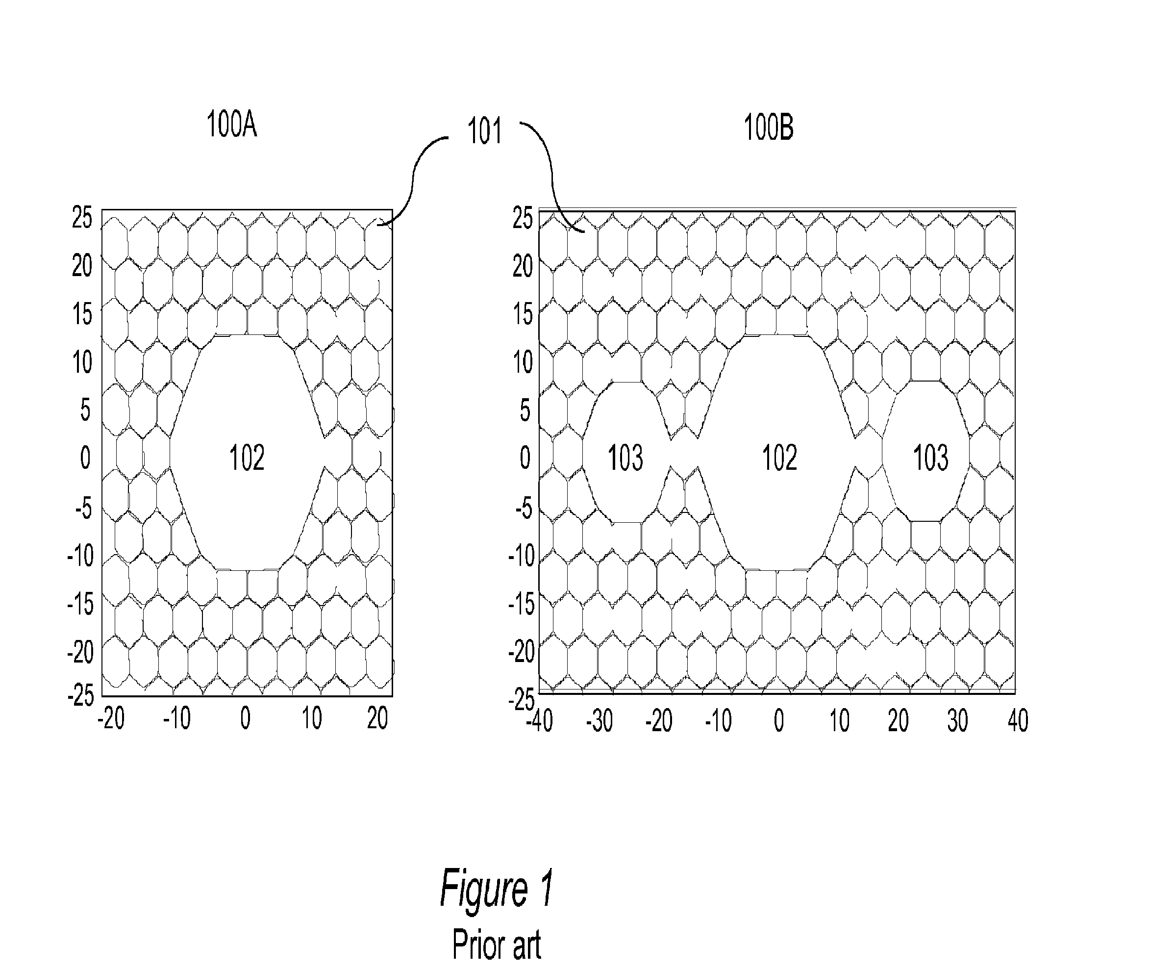
Despite any fiber variations, substantial index-mismatch exists between the signal mode and any shunt mode at substantially all positions along the fiber, such that any coupling of the signal mode over the total length of fiber is negligible.

Method used


Image

  • Shunt fiber
  • Shunt fiber
  • Shunt fiber

Examples


example a

37-Cell Core and 7-Cell Shunts

[0084]In an exemplary embodiment shown in FIG. 6, a 37-cell core, and 7-cell shunt fiber geometry is selected. More specifically, the fiber geometry shown in FIG. 6a comprises an array of lattice cells or lattice holes 601 with a lattice hole spacing of about 5.2 μm, providing a bandgap and low-loss guiding around 1550 nm. An air-fill-fraction in the lattice hole is about 95.5%. A central core region 602 is created by removing 37 lattice cells in the center in a “4-5-6-7-6-5-4” arrangement (37-cells core) and each of two shunts 603 (only one shown for clarity) has a 7-cell shape (7-cell shunt). The core-web thicknesses are adjusted to obtain a relatively surface-mode-free region in the calculation.

[0085]Results of effective index as a function of wavelength from simulation with a small amount of perturbations are plotted in the graphs shown in FIGS. 6b and 6c, respectively. In the effective index plots shown in FIGS. 6b and 6c, the fundamental modes 611...

example b

19-Cell Core and 7-Cell Shunts

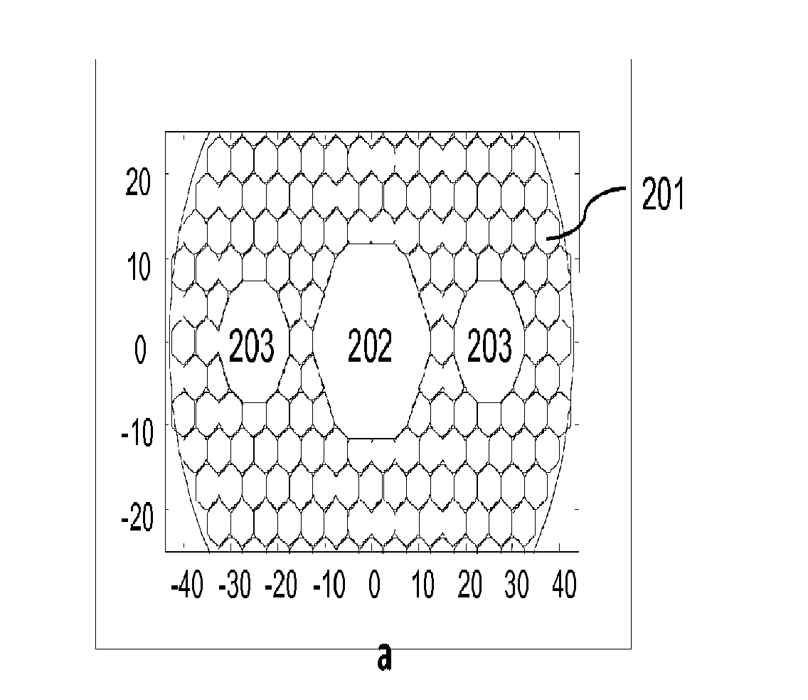
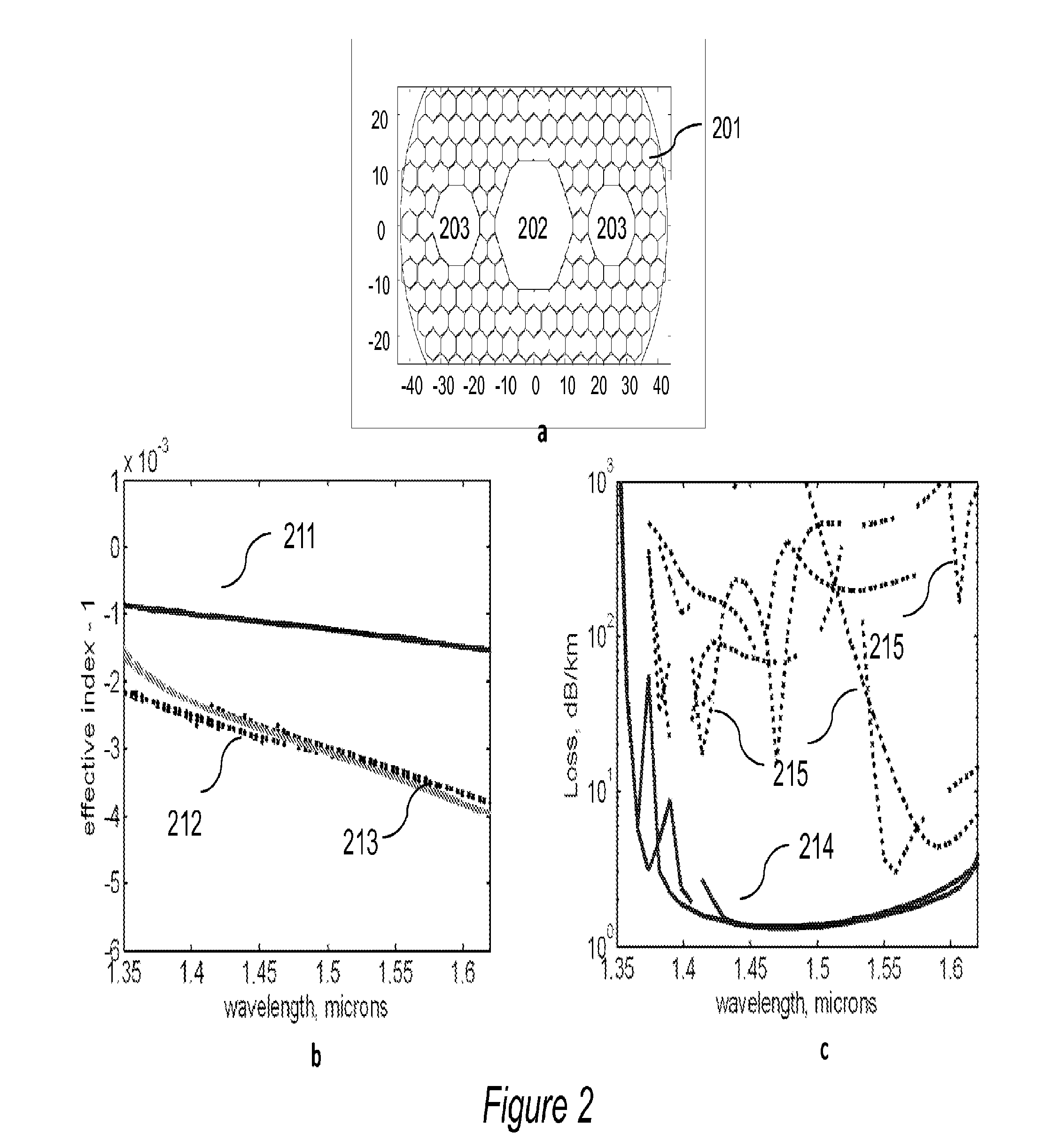
[0090]Shown in FIG. 7 are simulation results for an inventivefiber. The fiber geometry shown in FIG. 7a comprises an array of lattice cells or lattice holes 701 including a 19-cell core 702 and two 7-cell shunts 703 located symmetrically on either side of the core. The calculation assumes an idealized core and shunt geometry with a lattice hole spacing of about 4.9 μm, and an air-fill fraction of 95.5%. The simulation takes into account slight distortions from ideal circular shape for the core that may result in some surface modes. The simulation model also accounts for an index mismatch variation equivalent to a perturbation Δnpert=0.0007, that would result from a 7 cm bend diameter. As shown in FIG. 7b, shaded regions 714 (only one labeled) show perturbed shunt mode effective indices, and each shaded region surround a solid line 713 indicating the corresponding unperturbed shunt mode effective index.

[0091]The core and shunt sizes are selected such tha...


PUM


Abstract

Shunt fibers having a photonic bandgap cladding region including one or more hollow guiding regions of which one guiding region is configured as the core and one or more other guiding regions are configured as shunts, respectively, provide nearly single mode transmission in the core. The effective mode index of unwanted core modes and modes in one or more shunts are matched closely enough such that higher order modes will selectively couple to the shunt modes by resonant phase matching in the presence of fiber variations. The shunts are designed to have relatively higher losses thereby effectively dissipating power in the higher order modes at a faster rate.

Description

CROSS REFERENCE TO RELATED APPLICATIONS[0001]This application claims priority benefit from the Provisional Application No. 61 / 620,216, filed on Apr. 4, 2012, in the United States Patent and Trademark Office.STATEMENT REGARDING FEDERALLY SPONSORED RESEARCH AND DEVELOPMENT[0002]This invention was made with government support in part under a contract No. HR011-08-C-0019 granted by the Defense Advanced Research Projects Agency (DARPA). The government has certain rights in the invention. The views expressed are those of the inventors and do not reflect the official policy or position of the Department of Defense or the U.S. Government.BACKGROUND OF THE INVENTION[0003]1. Field of the Invention[0004]This application is related to the field of optical fiber and in particular, to large core-size Hollow Core Fiber (HCF) having Higher Order mode (HOM) suppression characteristics.[0005]2. Description of the Related Arts[0006]For several decades, commercial development of optical fibers has focu...

Claims


Application Information

Patent Timeline
Patent Type & Authority Applications(United States)
IPC IPC(8): G02B6/26G02B6/032G02B6/02
CPCG02B6/268G02B6/02047G02B6/032G02B6/02323G02B6/02338G02B6/14
Inventor FINI, JOHN MICHAELMENG, LINLIMONBERG, ERICNICHOLSON, JEFFREY WWINDELER, ROBERT
Owner OFS FITEL LLC
Learn More