
Electroseismic surveying in exploration and production environments

a technology of seismic surveying and production environment, applied in seismology for waterlogging, instruments, borehole/well accessories, etc., can solve the problems of preventing a full understanding of the location and extent of down-hole operations, requiring the use of expensive and/or time-consuming surveying equipment, and conventional surveying technologies. problems, to achieve the effect of avoiding the effect of problems

Active Publication Date: 2015-04-16
ES XPLORE L L C
View PDF1 Cites 36 Cited by
  • Summary
  • Abstract
  • Description
  • Claims
  • Application Information

AI Technical Summary

Benefits of technology

The present patent aims to provide a system for surveying a wellbore during drilling, fracturing, and production phases using passive electroseismic or seismoelectric techniques. This surveying system can detect signals generated in response to the well processes using a broad range of frequencies, resulting in high-resolution images of the subsurface earth formation and the well operation. The use of passive sources of electromagnetic or seismic energy reduces safety and environmental impacts, and the processing of the signals can identify various properties of the subsurface and well operation. The technical effects of the system include improved safety and reduced environmental impacts, cost savings, and improved imaging accuracy.

Problems solved by technology

These conventional surveying technologies, however, suffer from certain limitations that may prevent a full understanding of the location and extent of down-hole operations.
For example, particular surveying techniques may require the use of expensive and / or time consuming surveying equipment and methods that may limit the economic viability of surveying a particular prospective region.
In addition, particular technologies may be able to provide information regarding one or more geophysical properties of a subsurface region, but may not be able to provide information on other geophysical properties.
Such limitations may lead to the identification of prospective regions for drilling or exploration based on an incomplete and / or incorrect understanding of the prospective region, which may cause unnecessary time and / or expenses to be incurred exploring or drilling regions that do not have the desired geophysical properties.

Method used


Image

  • Electroseismic surveying in exploration and production environments
  • Electroseismic surveying in exploration and production environments
  • Electroseismic surveying in exploration and production environments

Examples


example processing

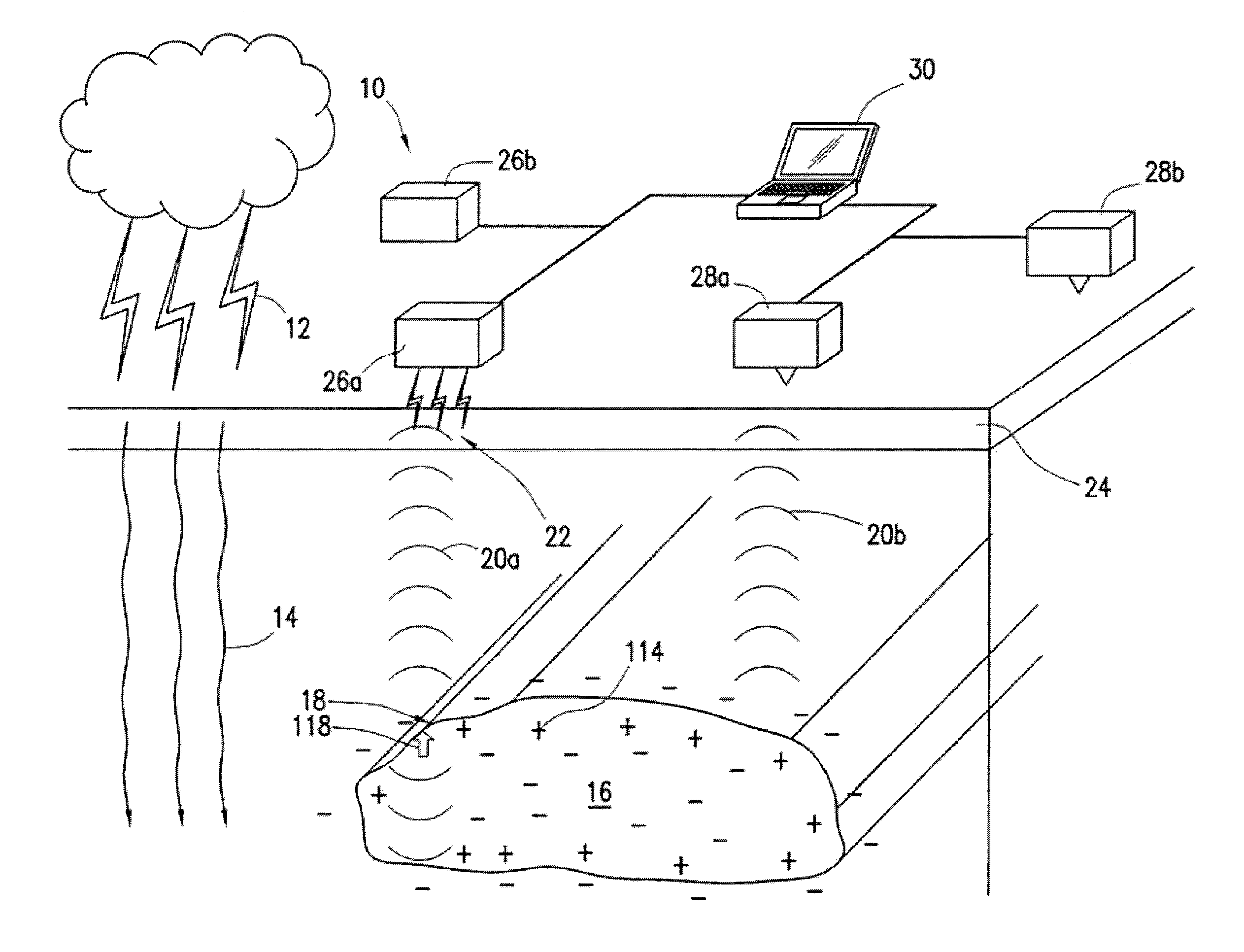
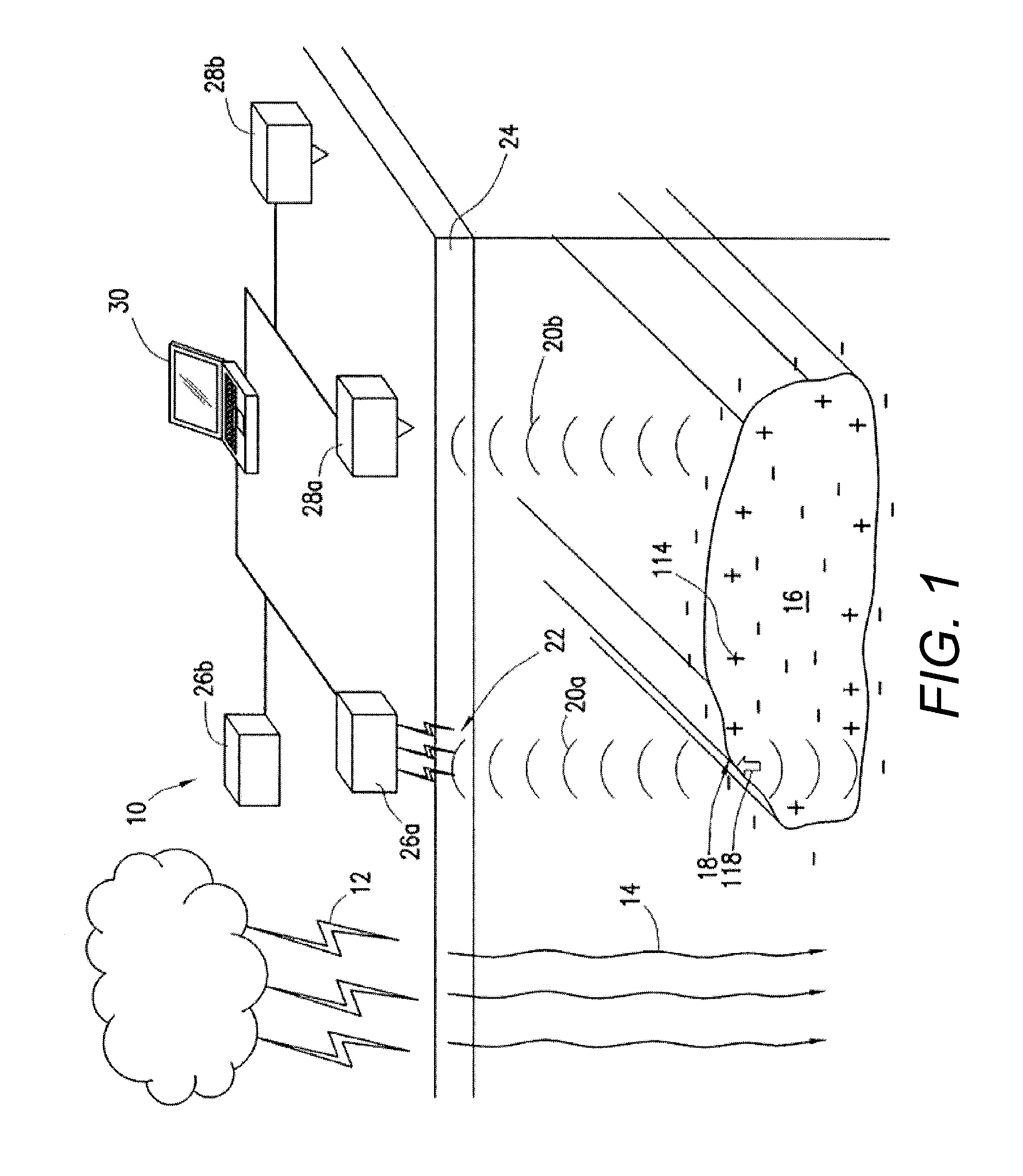
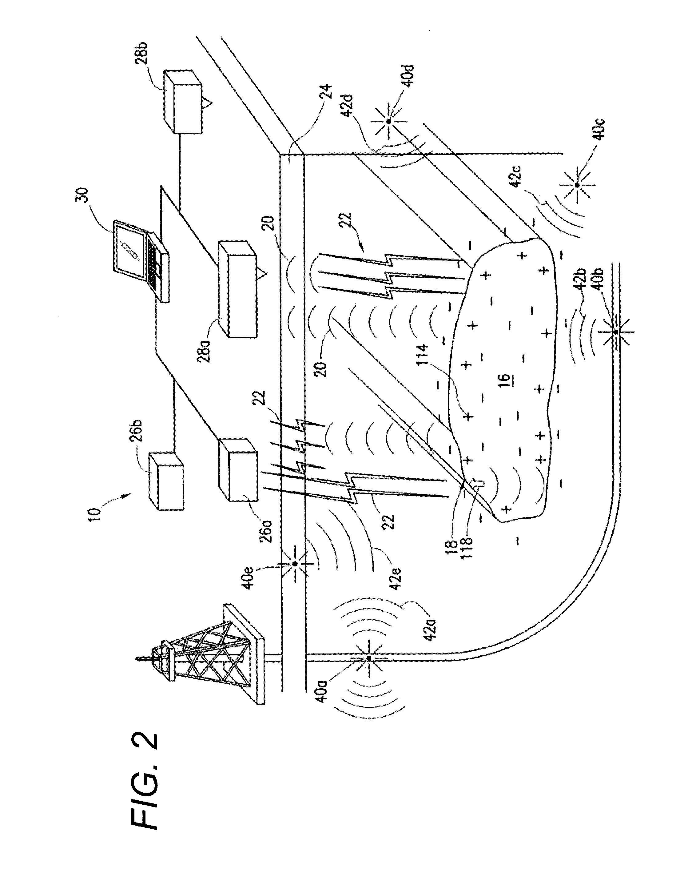
[0144 methods that may be performed at block 335 rely on the wave nature of a seismic wave. Seismic waves are reflected, transmitted, and refracted by the well-known Snell's laws. Waveform processing differs from much of electroseismic processing in that the wavelengths in the electromagnetic portion of an electroseismic signal is much larger than any structures of interest. In this case it may be appropriate to think of the electroseismic propagation problem in a low-frequency limit where there are no well-defined interface reflections.

[0145]Based on the signal received from one or more of the first sensor array, the second sensor array, and the third sensor array, and subsequent processing, as described above with respect to blocks 315-335, the computer system 30 determines one or more drillstring properties. One example drillstring property is the location of the drill bit. In certain example embodiments the location of the drill bit relative to a location at the surface or to a ...


PUM


Abstract

Systems, methods, and computer programs for monitoring a drilling operation in a subterranean formation include receiving, from a first sensor array, one or more seismic signals caused, at least in part, by the drilling operation in the subterranean formation; receiving, from the first sensor array, one or more electromagnetic signals generated by an electro seismic or seismoelectric conversion of the one or more seismic signals caused, at least in part, by the drilling operation in the subterranean formation; and determining a property of one or more of the drillstring and the subterranean formation based, at least in part, on the seismic signals and the corresponding electromagnetic signals received from the first sensor array. The first sensor array is arranged to monitor the drilling operation.

Description

CROSS-REFERENCE TO RELATED APPLICATIONS[0001]This application claim priority to U.S. Provisional Application No. 61 / 890,682 entitled “Electroseismic Surveying in Exploration and Production Environments” by Arthur Thompson, Alan Katz, Robert England, Todd W. Benson, and Mark Griffin, which was filed on Oct. 14, 2014, the contents of which are hereby incorporated by reference. This application claim priority to U.S. Provisional Application No. 61 / 891,096 entitled “Electroseismic Surveying in Production Environments” by Arthur Thompson, Alan Katz, Robert England, Todd W. Benson, and Mark Griffin, which was filed on Oct. 15, 2014, the contents of which are hereby incorporated by reference.BACKGROUND OF THE INVENTION[0002]Conventional techniques for the control of down-hole operations may rely on various models, sensors, heuristics, and operator judgment to determine, for example, the location of a drill bit in a subsurface formation or the propagation of fractures in the subsurface form...

Claims


Application Information

Patent Timeline
IPC IPC(8): G01V1/20G01V1/18G01V1/28
CPCG01V1/20G01V1/28G01V1/181G01V1/40G01V11/007G01V2210/32G01V2210/62G01V2210/624E21B49/00G01V1/306G01V2210/6224G01V2210/6244G01V2210/6246
Inventor THOMPSON, ARTHURKATZ, ALANENGLAND, ROBERTBENSON, TODD W.GRIFFIN, MARK
Owner ES XPLORE L L C
Learn More