Objective Optical System
- Summary
- Abstract
- Description
- Claims
- Application Information
AI Technical Summary
Benefits of technology
Problems solved by technology
Method used
Image

Examples
example 1
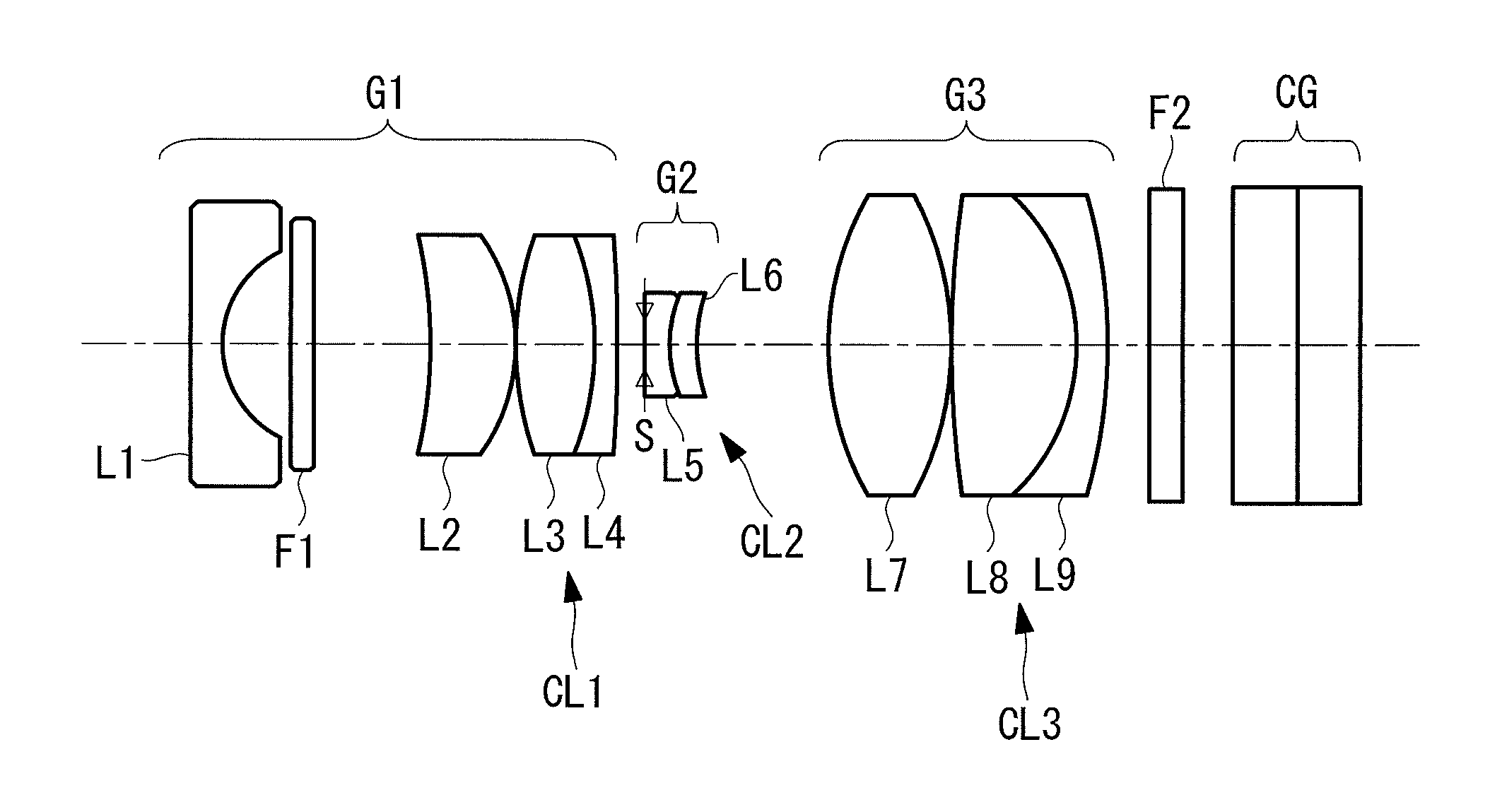
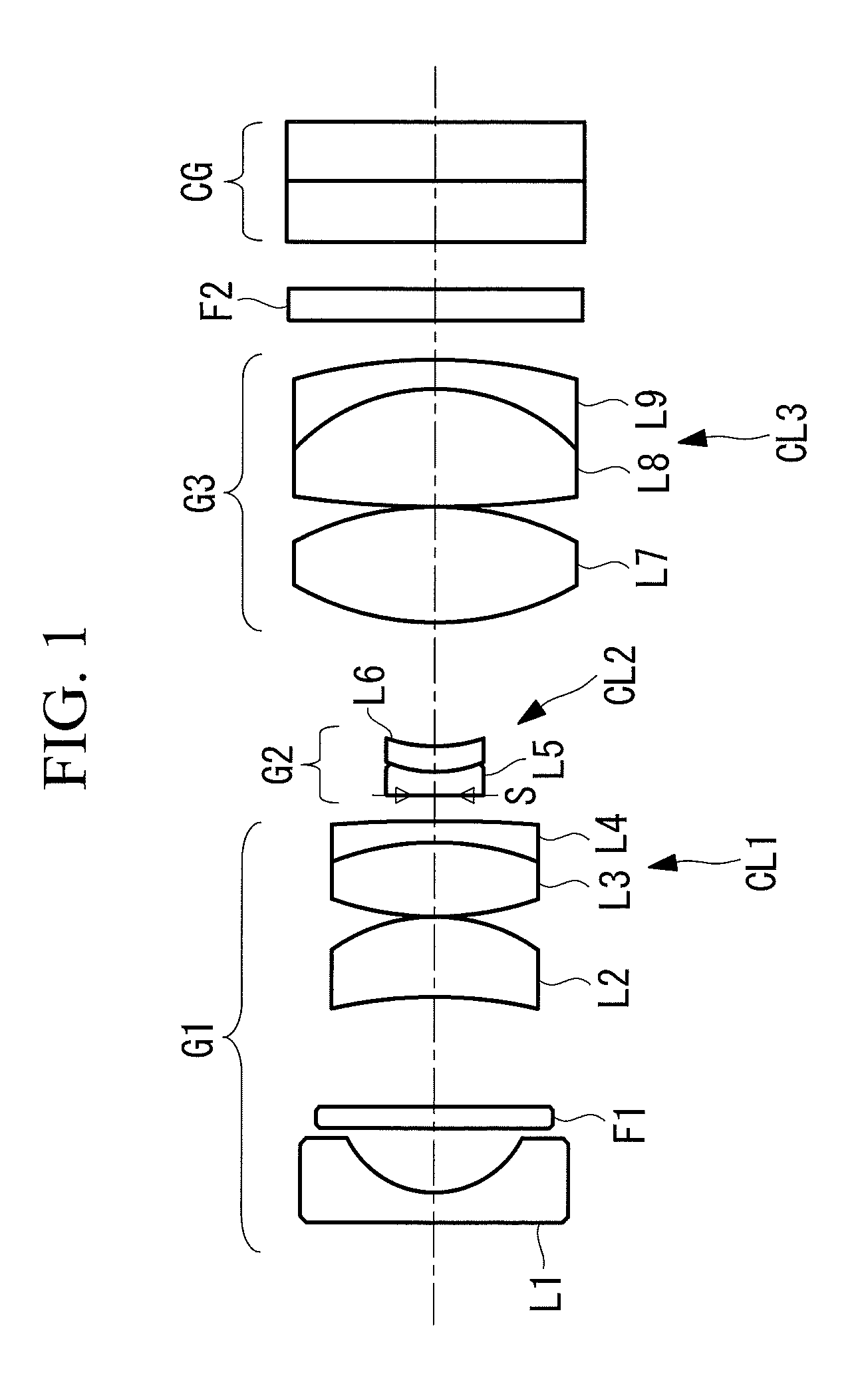
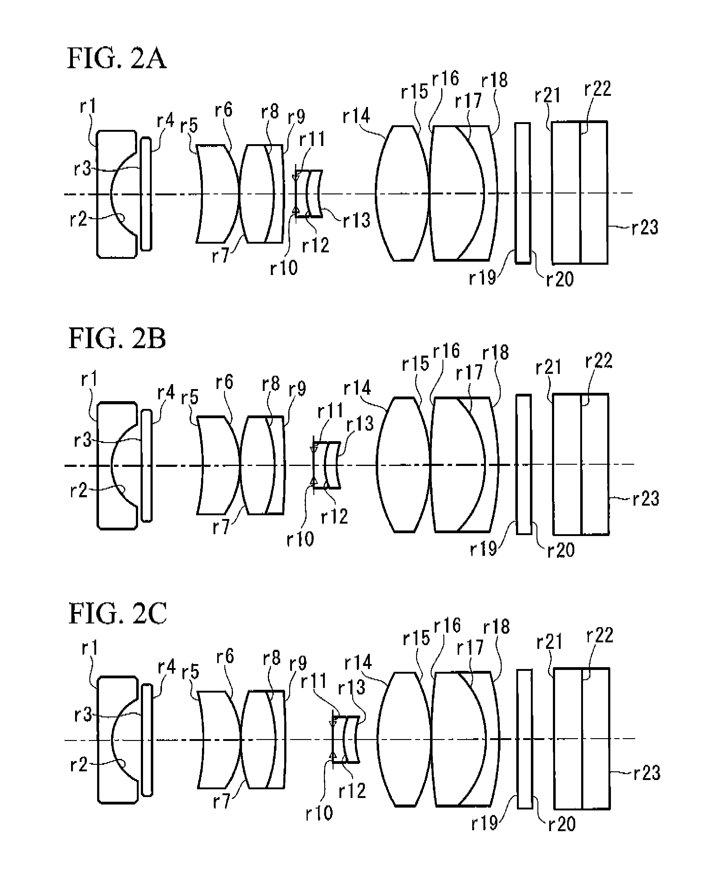
[0117]FIG. 2A, FIG. 2B, and FIG. 2C show the configuration of an objective optical system according to Example 1 of the present invention. FIG. 2A shows a normal observation state, FIG. 2B shows an intermediate state, and FIG. 2C shows a magnified observation state. FIG. 3 shows aberration diagrams of the objective optical system according to this Example in the normal observation state, FIG. 4 shows aberration diagrams in the intermediate state, and FIG. 5 shows aberration diagrams in the magnified observation state.
[0118]The lens data for the objective optical system according to Example 1 of the present invention is shown below.
Lens DataSurface numberrdNeVd1∞0.381.8881540.7621.3630.853∞0.311.5156475.004∞1.455−5.3551.051.6522233.796−2.3550.0374.0190.981.7762149.608−3.2960.301.9342918.909−19.843D9 10Aperture0.01stop11∞0.281.4891570.23121.4550.381.5966735.31131.912D13143.9151.521.4891570.2315−3.9150.041613.7041.541.4891570.2317−2.5840.421.9342918.9018−6.2440.5219∞0.401.5249859.8920∞...
example 2
[0119]FIG. 6A, FIG. 6B, and FIG. 6C show the configuration of an objective optical system according to Example 2 of the present invention. FIG. 6A shows a normal observation state, FIG. 6B shows an intermediate state, and FIG. 6C shows a magnified observation state. FIG. 7 shows aberration diagrams of the objective optical system according to this Example in the normal observation state, FIG. 8 shows aberration diagrams in the intermediate state, and FIG. 9 shows aberration diagrams in the magnified observation state.
[0120]The lens data for the objective optical system according to Example 2 of the present invention is shown below.
Lens DataSurfacenumberrdNeVd1∞0.381.8881540.7621.3960.853∞0.311.5156475.004∞1.455−4.1001.051.5197752.436−2.2550.0373.7590.981.7762149.608−3.7590.301.9342918.909−10.341D9 10Aperture0.018stop11∞0.2741.4891570.23121.4160.3131.5966735.31131.760D13143.8651.4941.4891570.2315−3.8650.039166.2241.5521.4891570.2317−2.9440.4111.9342918.9018−13.8230.35019∞0.3901.52498...
example 3
[0121]FIG. 10A, FIG. 10B, and FIG. 10C show the configuration of an objective optical system according to Example 3 of the present invention. FIG. 10A shows a normal observation state, FIG. 10B shows an intermediate state, and FIG. 10C shows a magnified observation state. FIG. 11 shows aberration diagrams of the objective optical system according to this Example in the normal observation state, FIG. 12 shows aberration diagrams in the intermediate state, and FIG. 13 shows aberration diagrams in the magnified observation state.
[0122]The lens data for the objective optical system according to Example 3 of the present invention is shown below.
Lens DataSurfacenumberrdNeVd1∞0.3651.8881540.7621.3900.7003∞0.6001.5150075.004∞1.0345−2.7961.1841.5197752.436−2.2770.02973.9211.0051.7762149.608−3.2590.2751.9342918.909−7.335D9 10Aperture0.025stop116.1550.2751.4891570.23121.5910.3141.5966735.31131.726D13143.3951.4311.4984681.5415−4.3530.0391624.3981.5691.4891570.2317−2.2930.3921.9342918.9018−6.117...
PUM
 Abstract
Description
Claims
Application Information
 - R&D
- Intellectual Property
- Life Sciences
- Materials
- Tech Scout
- Unparalleled Data Quality
- Higher Quality Content
- 60% Fewer Hallucinations
Browse by: Latest US Patents, China's latest patents, Technical Efficacy Thesaurus, Application Domain, Technology Topic, Popular Technical Reports.
© 2025 PatSnap. All rights reserved.Legal|Privacy policy|Modern Slavery Act Transparency Statement|Sitemap|About US| Contact US: help@patsnap.com