Directional coupler arrangement and method

Inactive Publication Date: 2015-04-16
HUAWEI TECH CO LTD
View PDF4 Cites 2 Cited by
  • Summary
  • Abstract
  • Description
  • Claims
  • Application Information

AI Technical Summary

Benefits of technology

The invention is about placing the coupler line of a directional coupler inside the air waveguide to make it more robust against manufacturing tolerances and improve its behavior with respect to insertion loss, directivity, operational bandwidth, and impedance matching. The air waveguide acts as a shield to reduce energy losses and improves manufacturing tolerances compared to a common directional coupler where energy transition points are not shielded. This makes the coupler arrangement easier to manufacture and improves its performance.

Problems solved by technology

When applying directional couplers together with air waveguides in radio transmission devices, manufacturing tolerances limit the performance of the transition between the electrical interface and the air interface.
In particular, manufacturing tolerances have a negative influence on operational bandwidth, directivity, and impedance matching of the directional coupler.

Method used


Image

  • Directional coupler arrangement and method
  • Directional coupler arrangement and method
  • Directional coupler arrangement and method

Examples


Embodiment Construction

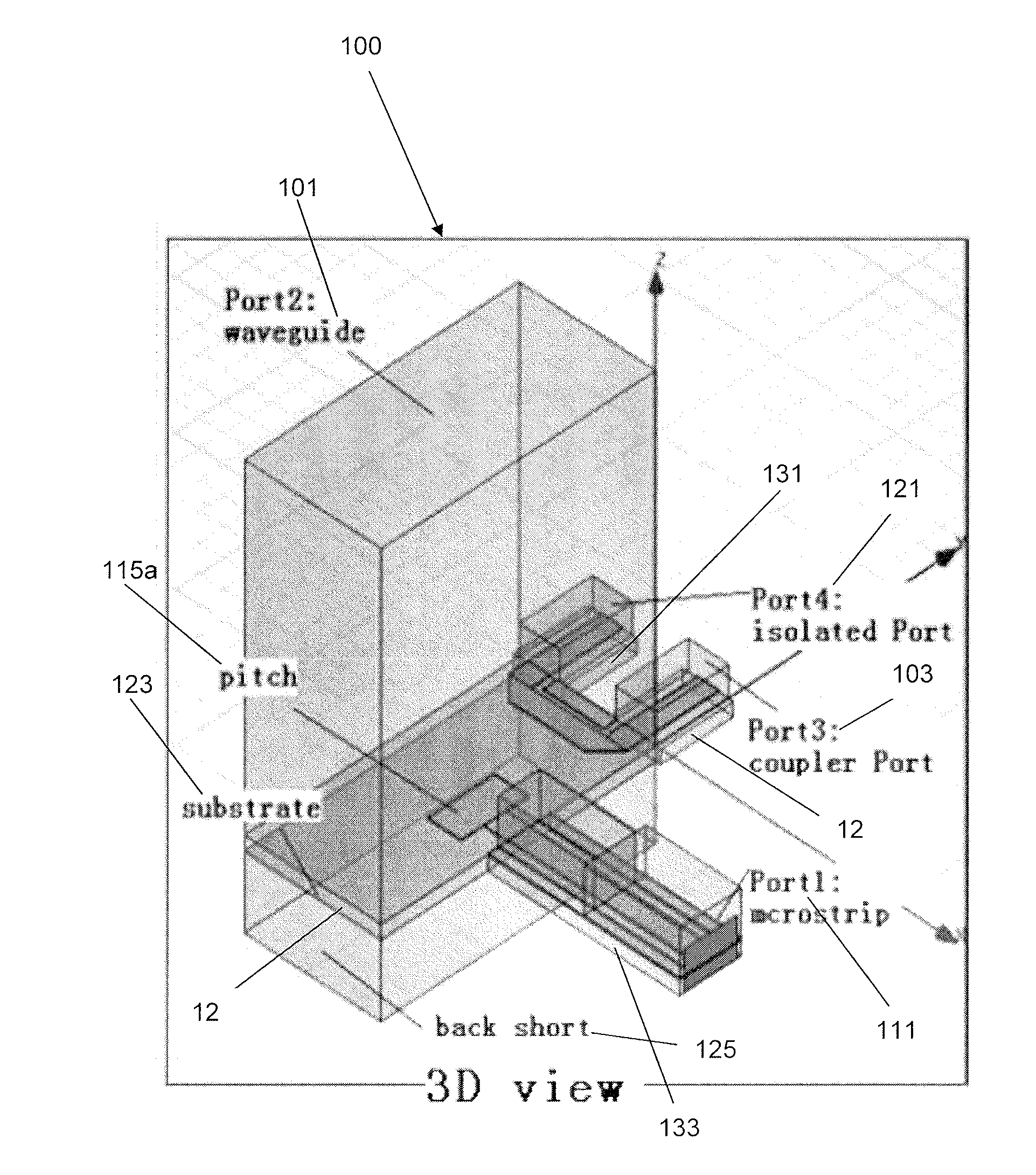
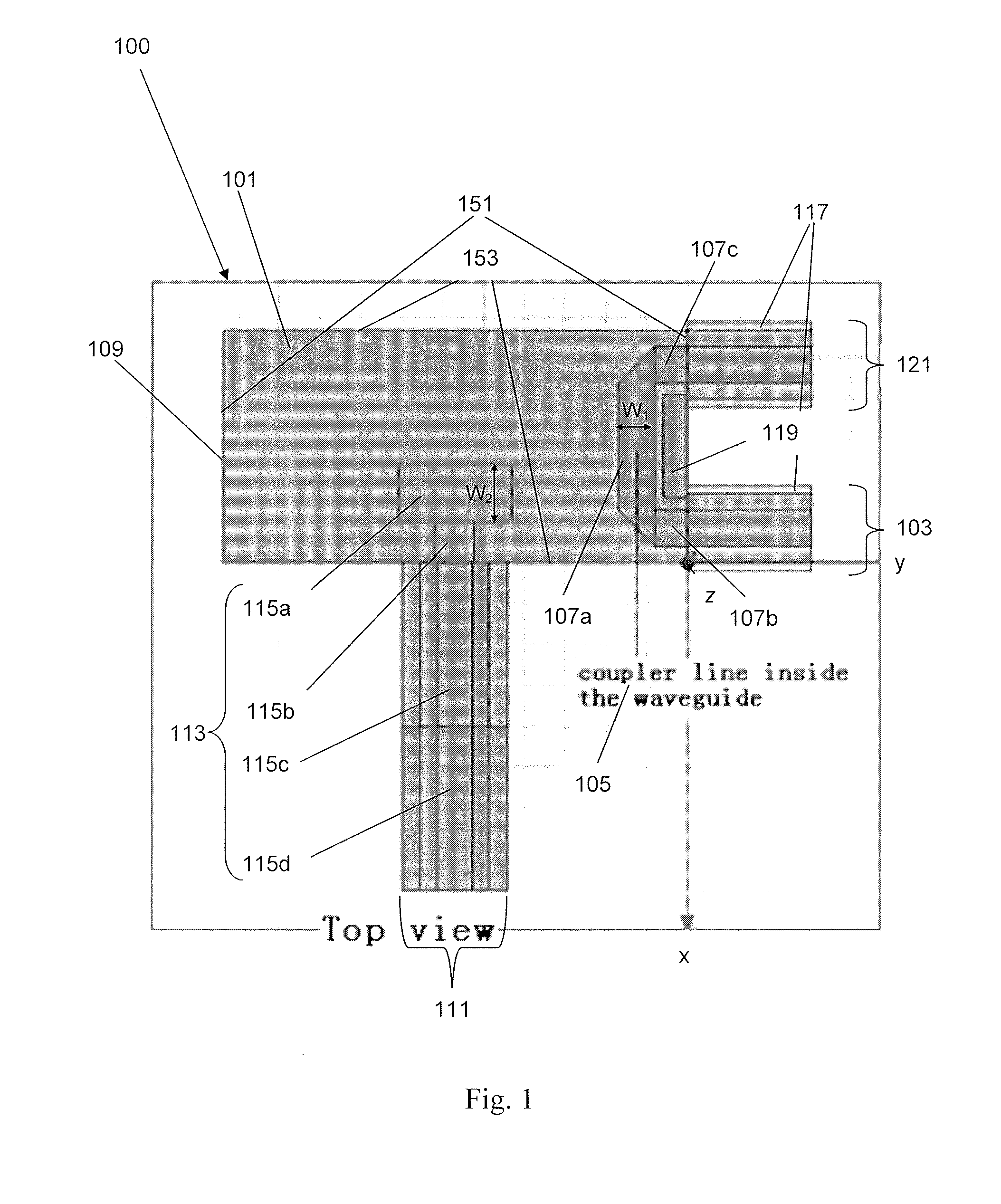
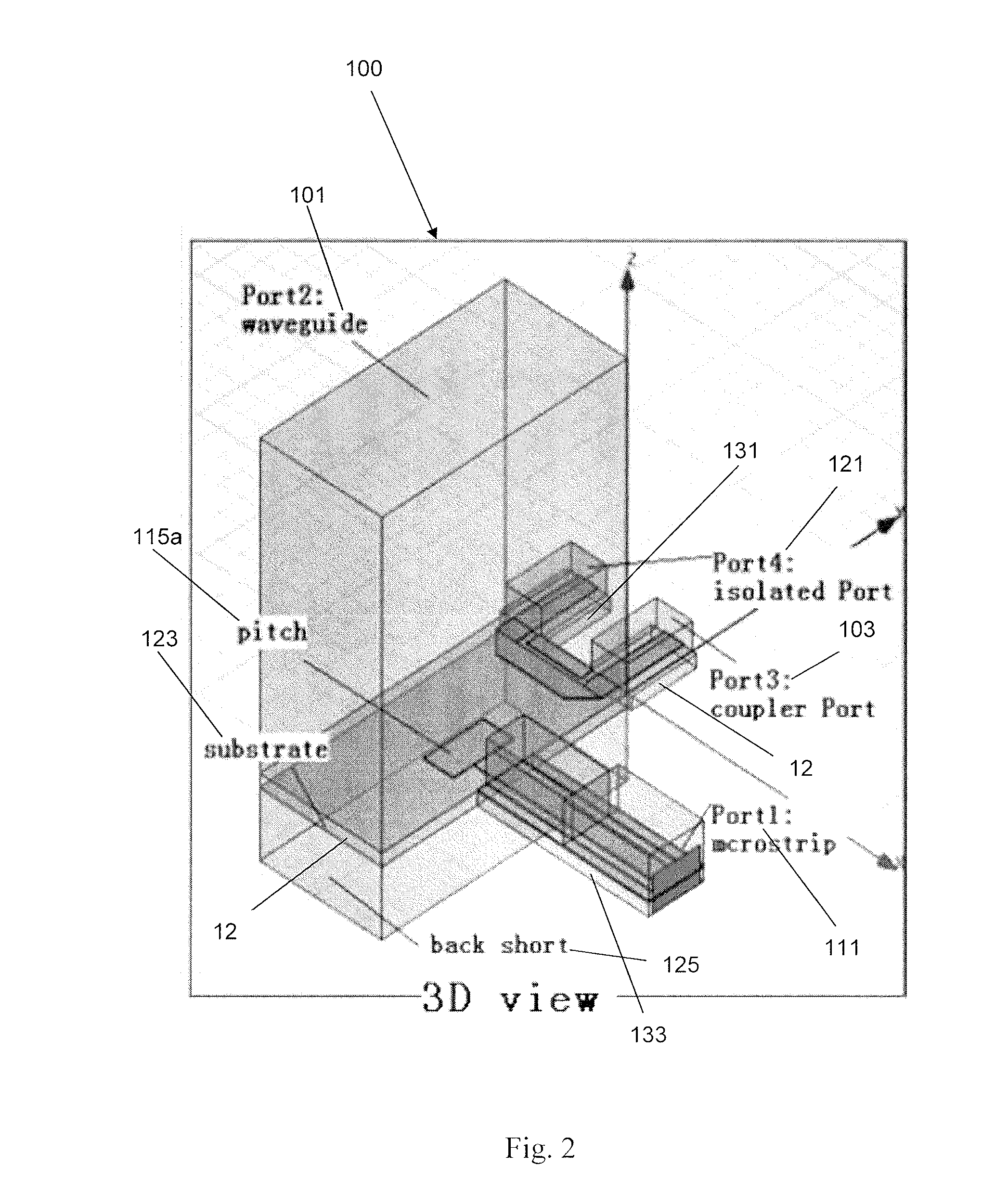
[0061]FIG. 1 shows a cross-sectional representation of a directional coupler arrangement 100 according to an implementation form. The directional coupler arrangement 100 comprises an air waveguide 101 and a coupler port 103. The coupler port 103 comprises a coupler line 105 which is arranged inside the air waveguide 101. The air waveguide 101 comprises a hollow body with metallic coating 109 and rectangular cross-section and is configured to guide electromagnetic waves within its body by reflection of the waves at the metallic coating 109. The cross-section may also have other geometrical forms, e.g. as square or circle, and the cross-section may vary in the direction z in which waves are guided by the air waveguide 101. The coupler line 105 is placed inside the air waveguide 101 and thereby in direct contact with electromagnetic waves traveling through the air waveguide 101. These electromagnetic waves induce a voltage in the coupler line 105 by electromagnetic induction such that ...


PUM

PropertyMeasurementUnit
Widthaaaaaaaaaa

Abstract

A directional coupler arrangement comprising an air waveguide and a coupler port having a coupler line arranged inside the air waveguide. A method for producing a directional coupler arrangement comprising forming an air waveguide and forming a coupler port having a coupler line arranged inside the air waveguide is also disclosed.

Description

CROSS-REFERENCE TO RELATED APPLICATIONS[0001]This application is a continuation of International Patent Application No. PCT / EP2012 / 061578, filed on Jun. 18, 2012, which is hereby incorporated by reference in its entirety.TECHNICAL FIELD[0002]The present invention relates generally to radio technology and specifically to directional coupler arrangements for waveguides. Even more specifically, the invention relates to a directional coupler arrangement where coupling to an air waveguide is within the air waveguide transition.BACKGROUND OF THE INVENTION[0003]Directional couplers (DCs) are passive devices used in the field of radio technology. They couple a defined amount of the electromagnetic power in a transmission line to another port where it can be used in another circuit. A feature of directional couplers is that they only couple power flowing in one direction. Power entering the output port is not coupled. Directional couplers are most frequently constructed from two coupled tran...

Claims


Application Information

Patent Timeline
IPC IPC(8): H01P5/18H01P11/00
CPCH01P5/181H01P5/184H01P11/002H01P11/003H01P5/107H01P5/185Y10T29/49016
Inventor SU, GUOYUMORGIA, FABIOMARCONI, FRANCO
Owner HUAWEI TECH CO LTD
Why Eureka
Try Eureka