
Reach Truck

a forklift and truck body technology, applied in the field of forklift trucks, can solve the problems of increased load, increased load, and increased load, and achieve the effect of facilitating the operation of the forklift truck, reducing load, and controlling the actual lowering speed

Active Publication Date: 2015-04-09
HYSTER YALE GRP
View PDF9 Cites 4 Cited by
  • Summary
  • Abstract
  • Description
  • Claims
  • Application Information

AI Technical Summary

Benefits of technology

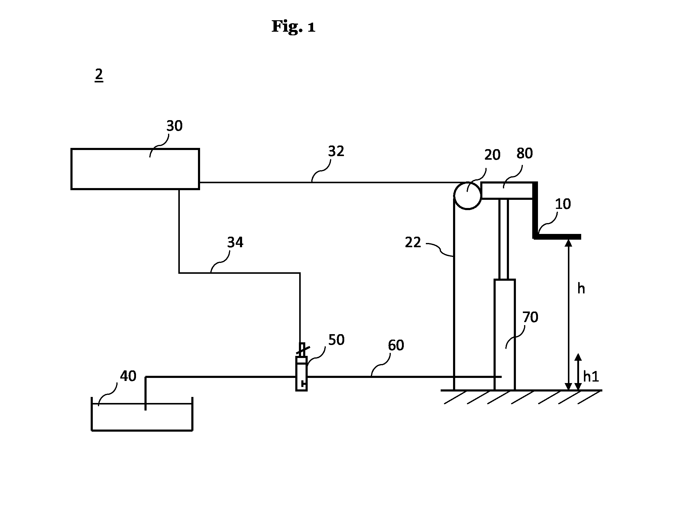
The patent describes a control system for a fork lift truck that allows for efficient and fast lowering of the fork without impacting the load. The control system uses a height sensor to measure the actual lifting height of the fork and a proportional electrical hydraulic valve to control the flow of hydraulic fluid during lowering. The control unit directly controls the valve based on the measured lifting height, ensuring precise control of the amount of hydraulic fluid flowing out of the lifting cylinder. The control system uses an exponential speed curve to maximize the speed of the fork during lowering and ensure a soft landing on the ground, preventing damage to the load. The control system is cost-efficient and reliable and can be adapted easily to different loads.

Problems solved by technology

For example it is known from prior art that the stability of forklift trucks tends to decrease with increasing lifting height or increasing load weight.
Such an impact is undesired since it might cause damages to handled loads, the reach truck and the ground, especially when heavy loads are handled.
However, such control systems have the disadvantage that the lowering speed of the fork depends on the load weight.
The heavier the load the faster the lowering speed will be.

Method used


Image

  • Reach Truck
  • Reach Truck
  • Reach Truck

Examples


Embodiment Construction

[0033]In the following, preferred embodiments of the invention are explained in detail described with reference to the figures.

[0034]A reach truck 1 which comprises a control system 2 is illustrated in FIG. 3. The reach truck 1 comprises an extendable mast 80 which carries a fork 10. The mast 80 of the reach truck 1 can be shifted back and forth by means of a mast trolley 110 as it is illustrated in FIG. 3 in dashed lines. This reach movement of the mast 80 enables that the fork 10 can reach below a pallet of goods (not shown) without moving the entire reach truck 1. The reach movement can be realized also by other means like a shift-able fork 10 for example by means of a pantograph arrangement.

[0035]An operator sitting in the operator cabin 100 steers and manually controls the reach truck 1. Particularly the operator manually controls the lowering speed v of the fork 10 in the normal operation mode. As time is critical the operator usually tries to lower the fork 10 as fast as poss...


PUM


Abstract

Reach truck 1 with a control system 2 for controlling the lowering movement of a fork 10, the control system 2 comprising a height sensor 20, for determining the lifting height h of the fork 10 of the reach truck 1, a proportional electrical hydraulic valve 50 connected to a lifting cylinder 70 of the reach truck 1, for controlling an oil flow of the lifting cylinder 70, and a control unit 30, connected to the height sensor 20 for receiving the actual lifting height h signal and controlling the proportional electrical hydraulic valve 50, wherein the control unit 30 automatically decreases the maximum lowering speed v of the fork 10, by controlling the proportional electrical hydraulic valve 50, according a predetermined maximum speed v curve depending on the lifting height h of the fork 10, and in some embodiments only on the lifting height h of the fork 10, such that the fork 10 is softly stopped at the ground.

Description

1. FIELD[0001]The present disclosure relates to a forklift truck, such as a reach truck, with a control system for controlling the lowering movement of a fork. Reach trucks are generally known in the prior art as a specific and common type of forklift trucks and are designed for warehouse operations.2. PRIOR ART[0002]Industrial vehicles for manufacturing and warehouse operations are known in the prior art, such as for example forklift trucks. Forklift trucks usually comprise an extendable mast at which a fork for reaching and carrying the load is supported. In warehouse applications it is desired that only the mast and the fork—and not the complete truck—moves forward and backwards to reach the load from a warehouse rack. To this end reach trucks are known, which are particularly designed for this specific task. Reach trucks comprise for example a mast that is shift-able back and forth in respect to the frame of the reach truck. Movable mast reach trucks comprise hydraulic systems a...

Claims


Application Information

Patent Timeline
Patent Type & Authority Applications(United States)
IPC IPC(8): B66F9/20B66F9/22
CPCB66F9/22B66F9/205B66F9/10B60P1/4471
Inventor HOOCK, MICHAEL
Owner HYSTER YALE GRP
Learn More