
Continuous galvanizing line

a technology of continuous galvanizing and zinc coating, which is applied in the direction of furnaces, heat treatment equipment, lighting and heating equipment, etc., can solve the problems of difficult to maintain the dew-point of an atmospheric gas in the furnace at 40° c. or lower, and the element wettability of hot dip zinc coating (zinc coatability) is markedly decreased, so as to prevent the surface oxidation of steel sheets with certainty and excellent zinc coatability

Active Publication Date: 2015-04-02
JFE STEEL CORP
View PDF19 Cites 6 Cited by
  • Summary
  • Abstract
  • Description
  • Claims
  • Application Information

AI Technical Summary

Benefits of technology

This patent is about a continuous galvanizing line that prevents the oxidation of steel sheets during annealing. The line includes a radiant tube heating type annealing furnace, a moisture removal device, dew-point meters, and inlets for controlling the dew-point of the atmospheric gas. By controlling the dew-point, the line can prevent oxidation of the steel sheet surface and produce a more zinc coatable galvanized steel sheet. This patent is useful for manufacturing high-quality galvanized steel sheets.

Problems solved by technology

However, there is a problem in that, since the chemical elements described above such as Si and Mn are elements which are easily oxidized, these chemical elements markedly decrease the wettability of hot dip zinc coating (zinc coatability).
However, there is a problem in that, since it is impossible to include an oxidation process in an annealing furnace of an all radiant tube heating type, it is impossible to achieve good zinc coatability of a steel sheet which contains chemical elements such as Si and Mn.
However, although it is disclosed that a dew-point is controlled to −40° C. or lower in this method and that a specific method for achieving the specified dew-point is to absorb and remove the moisture in the furnace with an absorbent, it is difficult to steadily keep the dew-point of an atmospheric gas in the furnace at −40° C. or lower.
Therefore, there is a problem in that it is impossible to steadily manufacture a high strength galvanized steel sheet having excellent zinc coatability by only using the method disclosed in Patent Literature 2.
However, since the object of this method is to reduce the time required to start up a bright annealing furnace for stainless steel at the beginning of its operation or at the resumption of its operation after repair, there is no mention of the improvement of the zinc coatability of the surface of a steel sheet.
However, although it is disclosed that a dew-point is controlled in this method, this is a method for improving zinc coatability by using oxidation-reduction reaction in the non-oxidation furnace and the reducing furnace, which means that this is not a method which can be applied to a furnace of an all radiant tube heating type in which the surface of a steel sheet is not positively reduced.
However, the object of the refining device of this annealing line is to prevent defective coloring of the surface of the metal strip which occurs when the thickness of the strip is switched between thin and thick gauges, and not to improve zinc coatability.

Method used


Image

  • Continuous galvanizing line
  • Continuous galvanizing line
  • Continuous galvanizing line

Examples


examples

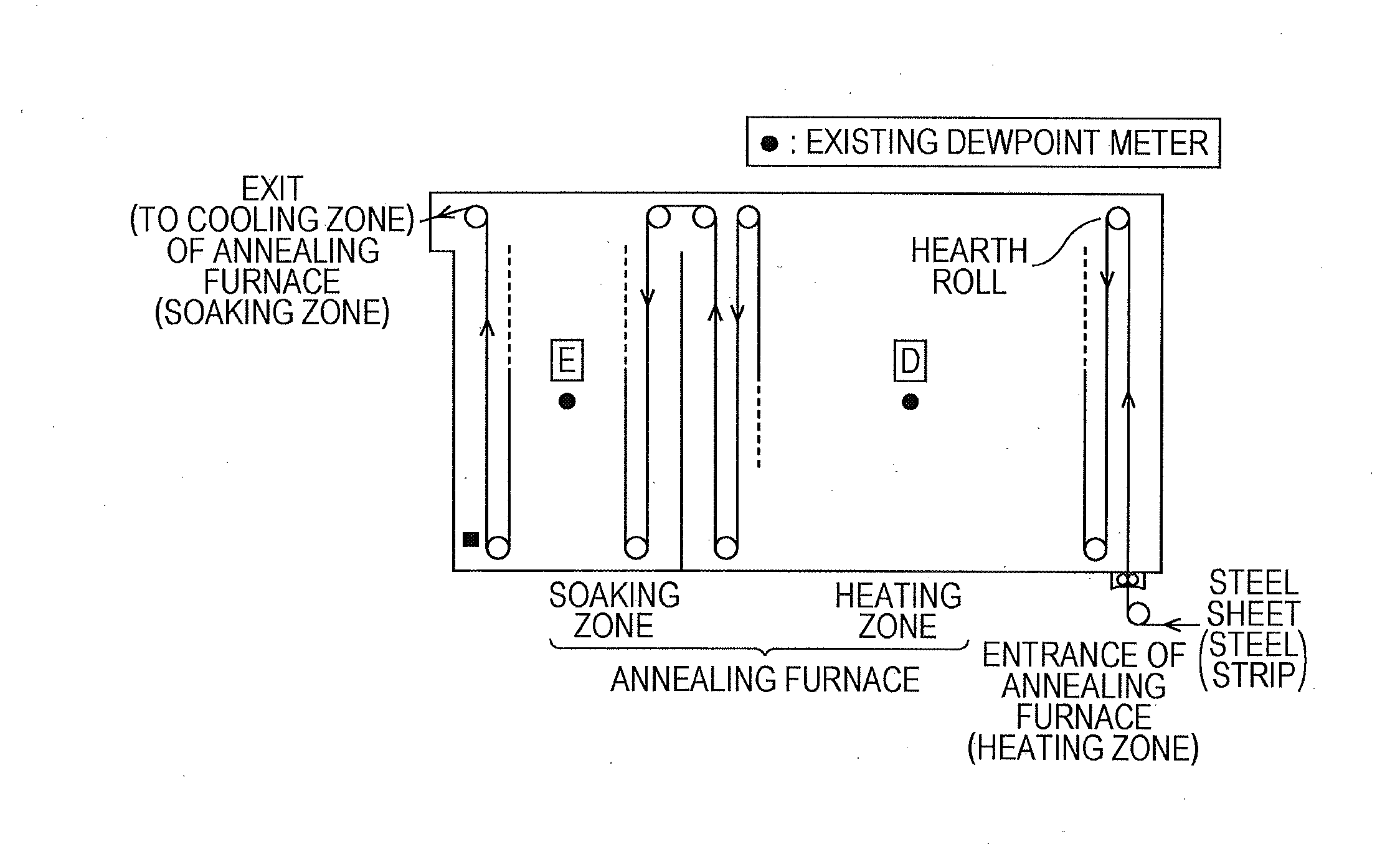
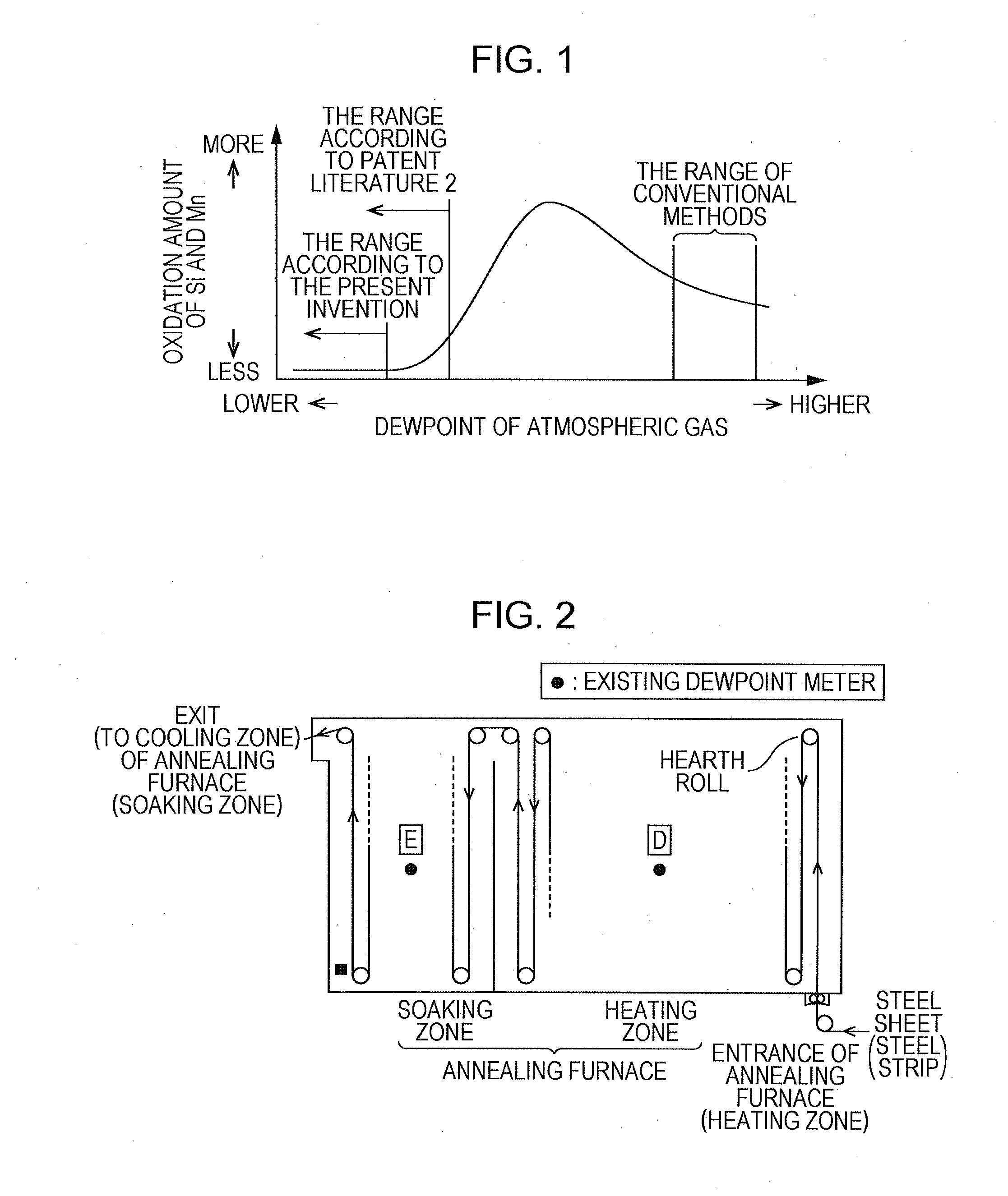
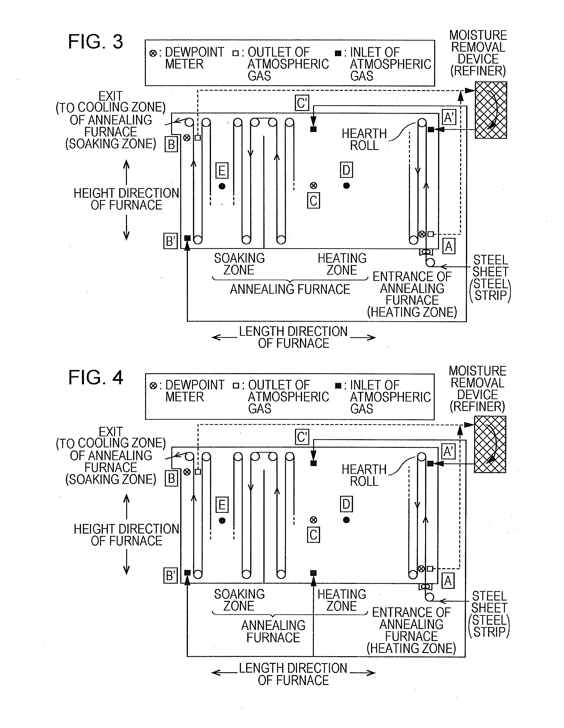
[0042]By using a galvanizing line (comparative example) consisting of an annealing furnace illustrated in FIG. 2 which consists of dew-point meters placed at the central position of the heating zone and the soaking zone and in which the dew-point of the atmospheric gas in the furnace is controlled to be −40° C. or lower, and by using a galvanizing line (example of the present invention) consisting of an annealing furnace illustrated in FIG. 3 which consists of, in addition to the line illustrated in FIG. 2, dew-point meters with which the dew-point of the atmospheric gas is observed, outlets through which the atmospheric gas in the furnace is collected and inlets through which the atmospheric gas from which moisture has been removed with the moisture removal device described above is fed into the furnace, the dew-point meters and the outlets being placed at least at two points which respectively exist on the side wall in the vicinity of the entrance of the annealing furnace and on t...


PUM

PropertyMeasurementUnit
temperatureaaaaaaaaaa

Abstract

A continuous galvanizing line having an annealing furnace of an all radiant tube heating type includes a moisture removal device, dew-point meters, outlets through which the atmospheric gas in the furnace is collected and inlets through which the atmospheric gas from which moisture has been removed with the moisture removal device is fed into the furnace, the dew-point meters and the outlets being placed at least at two points which respectively exist on a side wall in the vicinity of the entrance of the annealing furnace and on a side wall in the vicinity of the furnace top or the furnace bottom at a position where a steel sheet has a maximum end-point temperature, the inlets being placed at two points which respectively exist on side walls on the sides opposite to the sides of the two points for the outlets in the height direction of the furnace, making it possible to steadily control the dew-point of the atmospheric gas to be −45° C. or lower and −80° C. or higher throughout the whole area of the annealing furnace.

Description

CROSS REFERENCE TO RELATED APPLICATIONS[0001]This is the U.S. National Phase application of PCT / JP2013 / 001156, filed Feb. 27, 2013, which claims priority to Japanese Patent Application No. 2012-087313, filed Apr. 6, 2012, the disclosures of each of these applications being incorporated herein by reference in their entireties for all purposes.FIELD OF THE INVENTION[0002]The present invention relates to a continuous galvanizing line and, specifically, a continuous galvanizing line consisting of an annealing furnace of an all radiant tube heating type which can be ideally used for manufacturing a galvanized steel sheet and a galvannealed steel sheet having excellent zinc coatability.BACKGROUND OF THE INVENTION[0003]Nowadays, in the fields of, for example, automobiles, home electrical appliances and building material industries, surface treated steel sheets which are manufactured by providing untreated steel sheets with corrosion resistance, in particular, galvanized steel sheets and ga...

Claims


Application Information

Patent Timeline
Patent Type & Authority Applications(United States)
IPC IPC(8): C23C2/40F27D7/06F27D99/00C23C2/00C23C2/02
CPCC23C2/40C23C2/003F27D7/06F27D99/0001C23C2/02C21D1/76G01N25/66C23C2/06C21D8/0473C21D9/561F27B9/28F27D2007/063C21D9/48C21D1/26C21D8/0436C23C2/00C23C2/0038C23C2/022C23C2/52C21D9/56C23C2/544B05C11/1015
Inventor SATO, NOBUYUKI
Owner JFE STEEL CORP
Learn More