
Choke

a choke and inductance value technology, applied in the field of chokes, can solve the problems of large inductance value variation of the choke, low yield, and high labor cost of the manufacturing process of the choke, and achieve the effect of small inductance value variation and high assembly stability

Active Publication Date: 2015-04-02
CYNTEC
View PDF6 Cites 1 Cited by
  • Summary
  • Abstract
  • Description
  • Claims
  • Application Information

AI Technical Summary

Benefits of technology

The solution reduces labor costs, enhances assembly stability, minimizes inductance value variations, and allows for the use of the same core for chokes with different inductances, while preventing magnetic material overflow and improving efficiency.

Problems solved by technology

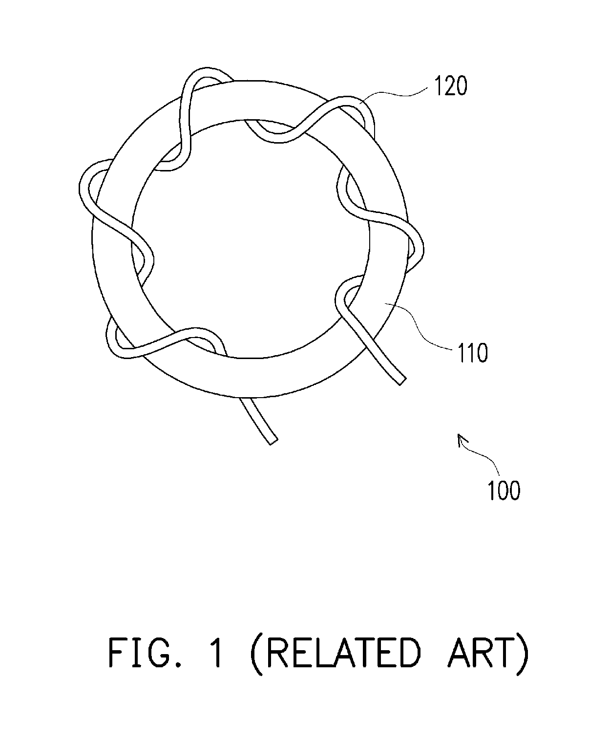
As the choke 100 needs to be produced by winding the wire 120 on the toroidal core 110 manually instead of being produced automatically, the manufacturing process of the choke 100 requires a considerable labor cost.
However, if the control of the amount of the adhesive is undesirable or the surface of an assembling face of the core is uneven in the assembly, the thickness of the adhesive after the assembly may easily become non-uniform, thus resulting in a large inductance value variation of the choke and obtaining a low yield.
In order to solve the above problem, a special surface treatment procedure is proposed for enhancing the assembly precision and enlarging the assembling face of the core, but the manufacturing cost of the choke is increased accordingly.

Method used


Image

  • Choke
  • Choke
  • Choke

Examples


Embodiment Construction

[0075]Reference will now be made in detail to the present embodiments of the invention, examples of which are illustrated in the accompanying drawings. Wherever possible, the same reference numbers are used in the drawings and the description to refer to the same or like parts.

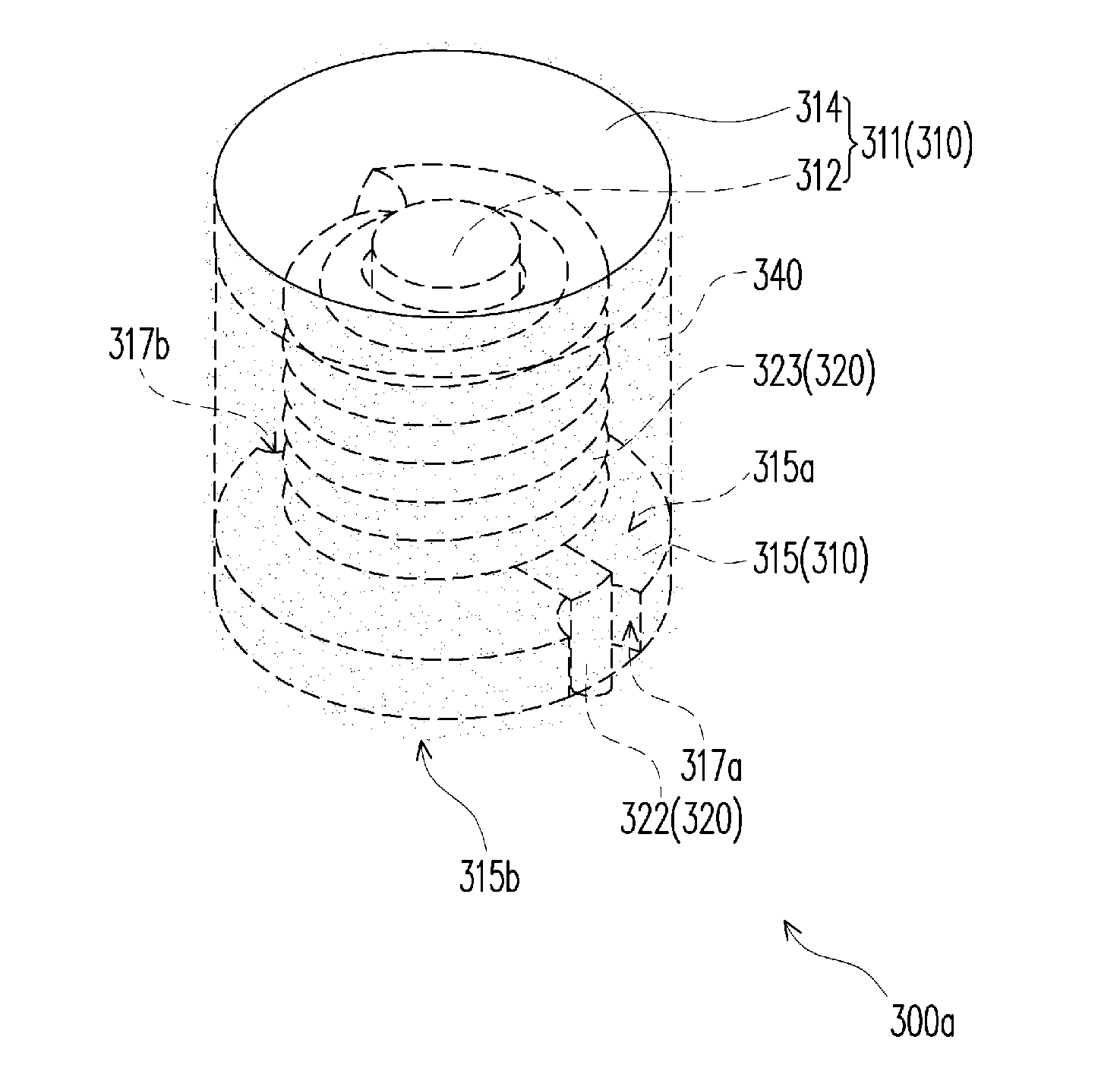
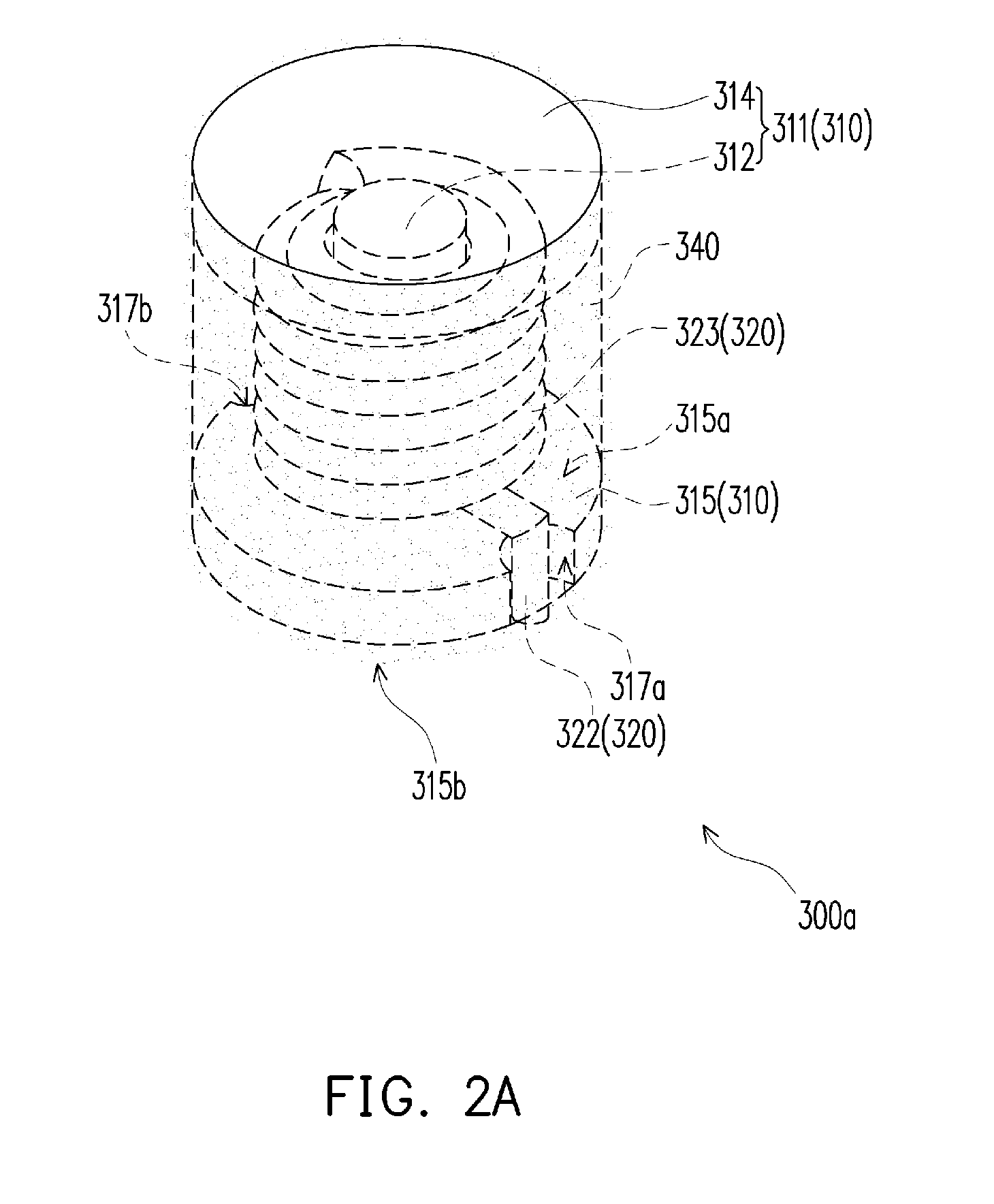
[0076]FIG. 2A is a schematic view of a choke according to an embodiment of the present invention, FIG. 2B is a schematic exploded view of the choke in FIG. 2A, and FIG. 2C is a schematic bottom view of the choke in FIG. 2A. First referring to FIGS. 2A and 2B, in this embodiment, the choke 300a includes a core 310 and a hollow coil 320. The core 310 includes a first core body 311 and a second core body 315.

[0077]The first core body 311 includes a pillar 312 and a top plate 314. An end 312b of the pillar 312 is connected to the top plate 314 to form a T-shaped structure. The pillar 312 and the top plate 314 are integrally formed. The second core body 315 is a flat plate and has a joining face 315a, an assembling...


PUM

PropertyMeasurementUnit
temperatureaaaaaaaaaa
heightaaaaaaaaaa
thicknessaaaaaaaaaa

Abstract

A method to form a choke is disclosed, wherein the method comprises: encapsulating a hollow coil by a molding body; forming a first core, wherein the first core comprises a pillar; and disposing at least one first portion of the pillar inside the encapsulated hollow coil. The method avoids the overflow or vertical flow issue during a molding process for encapsulating a coil that has been wound on a core already.

Description

CROSS-REFERENCE TO RELATED APPLICATION[0001]This application is a divisional of U.S. application Ser. No. 12 / 642,327, filed Dec. 18, 2009, which claims the priority benefit of Taiwan application serial no. 98119066, filed on Jun. 8, 2009. Each of the above-mentioned patent applications is hereby incorporated by reference herein and made a part of this specification.BACKGROUND OF THE INVENTION[0002]1. Field of the Invention[0003]The present invention generally relates to a passive device, in particular, to a choke.[0004]2. Description of Related Art[0005]A choke functions to stabilize a current in a circuit and achieve the effect of filtering noises. The function of the choke is similar to that of a capacitor, i.e., both for regulating the stability of the current by storing and releasing electric energy in the circuit. Compared with the capacitor that stores electric energy in the form of an electric field (charges), the choke achieves the same purpose in the form of a magnetic fiel...

Claims


Application Information

Patent Timeline
Patent Type & Authority Applications(United States)
IPC IPC(8): H01F41/00H01F17/04H01F27/02
CPCH01F41/005H01F2017/048H01F17/04H01F27/022H01F3/10H01F17/045Y10T29/49073
Inventor HSIEH, LAN-CHINHSIEH, ROGERKUO, YU-CHINGLIU, CHUN-TIAO
Owner CYNTEC
Learn More