
Engine cover

a technology for engine covers and hoods, which is applied in the direction of machines/engines, mechanical equipment, combustion air/fuel air treatment, etc., can solve the problems of increased manufacturing costs and difficulty in providing the space for allowing the bonnet to be opened, and achieves high assembly stability, easy installation operation, and cheap manufacturing.

Inactive Publication Date: 2006-04-06
TOYODA GOSEI CO LTD
View PDF8 Cites 26 Cited by
  • Summary
  • Abstract
  • Description
  • Claims
  • Application Information

AI Technical Summary

Benefits of technology

[0012] The present invention has been developed in view of the aforementioned circumstances. It is therefore an object of the present invention to provide an engine cover, which can be manufactured inexpensively, and which can provide a space for permitting a bonnet hood to deform between the bonnet hood and the engine cover satisfactorily.
[0025] The present engine cover can produce a satisfactory space between itself and a bonnet food, because the cover body approaches the engine when the cover body is subjected to a downward load, that is, in collisions. Accordingly, the present engine cover can provide a space between itself and the bonnet hood, space which is adapted for permitting the bonnet hood to deform satisfactorily. Specifically, when the deforming bonnet cover interferes with the present engine cover to apply a load of 2,000 N or less to the engine cover, the cover body approaches the engine to secure a space for permitting the bonnet hood to deform satisfactorily. Consequently, it is possible to absorb the shocks in collisions, because the present engine cover allows the bonnet hood to deform satisfactorily.
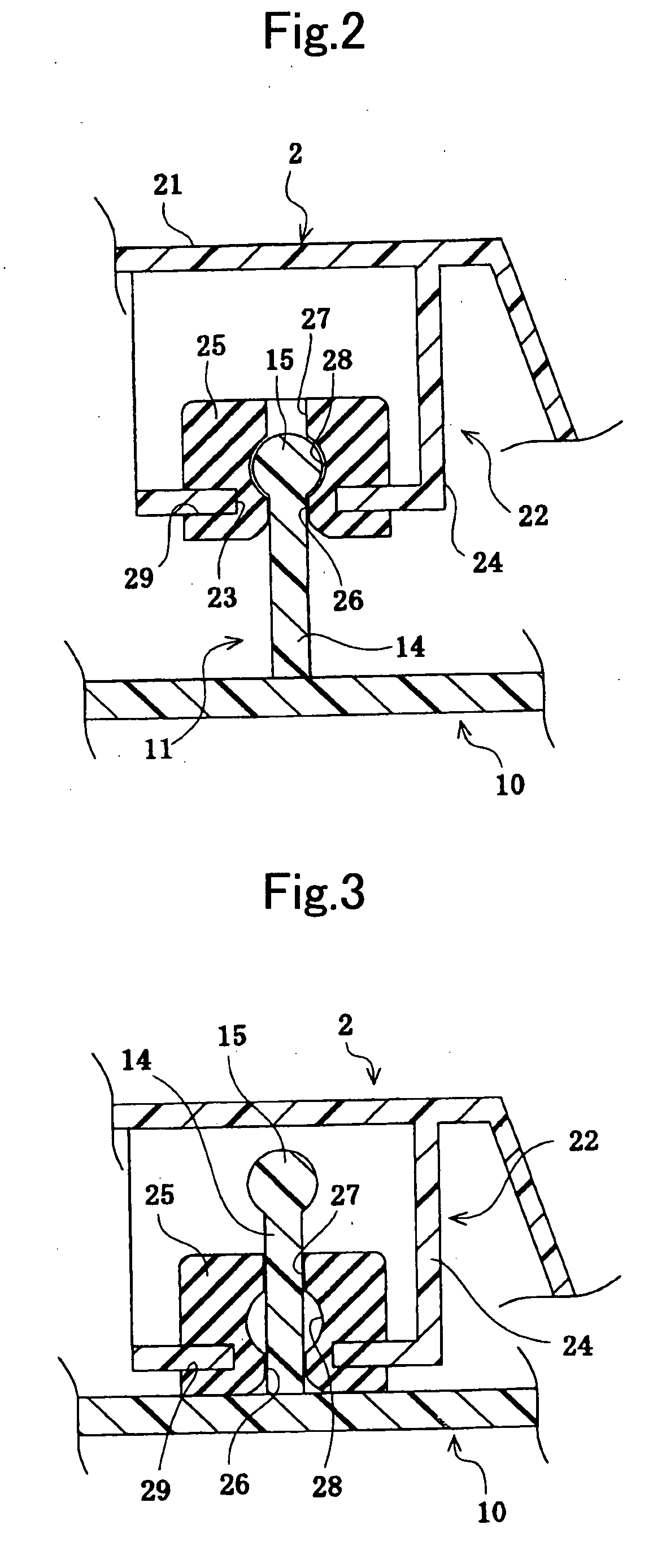
[0026] The present engine cover is installed to the engine in the following manner. The head, a constituent member of one of the installation member and installed member, engages with the inner peripheral surface of the diametrically-enlarged intermediate hole in the elastic member, a constituent member of the other one of the installation member and installed member. When the present engine cover is subjected to loads, that is, in collisions, the head goes through the diametrically-enlarged intermediate hole, or the elastic member deforms to elongate around the diametrically-enlarged intermediate hole so that the head moves toward the second hole of the elastic member. Accordingly, the cover body of present engine cover approaches the engine. Thus, the present engine cover comprises the installation member disposed on the engine and the installed member disposed on the cover body, installation member and installed member which have simplified constructions, respectively. Consequently, the present engine cover can be manufactured inexpensively.
[0027] Moreover, the present engine cover produces an advantage of making the installation operation easier, because it can be installed to the engine by simply engaging the installation member with the installed member.
[0028] In the present engine cover, when the outside diameter D1 of the head and the inside diameter D2 of the second hole satisfy a relational expression, D2 / D1≦0.75, the present engine cover can be held to the engine stably, that is, the present engine cover can demonstrate high assembly stability, because the head hardly goes through the diametrically-enlarged intermediate hole even when the present engine cover is subjected to minor loads resulting from vibrations during travelling, for example. On the other hand, when the outside diameter D1 of the head and the inside diameter D2 of the second hole satisfy a relational expression, 0.2≦D2 / D1, the present engine cover can securely produce the space for permitting the bonnet hood to deform in collisions, that is, the present engine cover can demonstrate high pedestrian-protective performance, because no excessive load is needed to let the head go through the diametrically-enlarged intermediate hole in order to approach the cover body the engine. Moreover, when the outside diameter D1 and the inside diameter D2 satisfy a relational expression, 0.2≦D2 / D1≦0.75, the present engine cover can satisfy both high pedestrian-protection performance and high assembly stability at the same time.
[0029] Note that it is advisable that the load for moving the head toward the second hole can be 2,000 N or less in order to give the present engine cover much better pedestrian-protective performance.

Problems solved by technology

Accordingly, there might arise a problem that it is difficult to provide the space for permitting the bonnet hood to deform to a satisfactory size.
However, the engine cover might be associated with a problem that the manufacturing cost goes up, because it requires many expensive component parts, such as the fracturable collar upon being subjected to a predetermined load, and the hollow member in which a fluid is filled.

Method used


Image

  • Engine cover
  • Engine cover
  • Engine cover

Examples


examples

[0043] Hereinafter, the present invention will be described in detail with reference to the accompanying drawings showing an engine cover according to an example of the present invention.

example no.1

Example No. 1

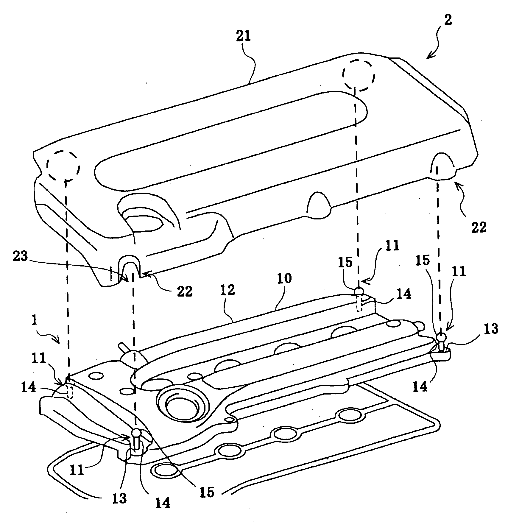
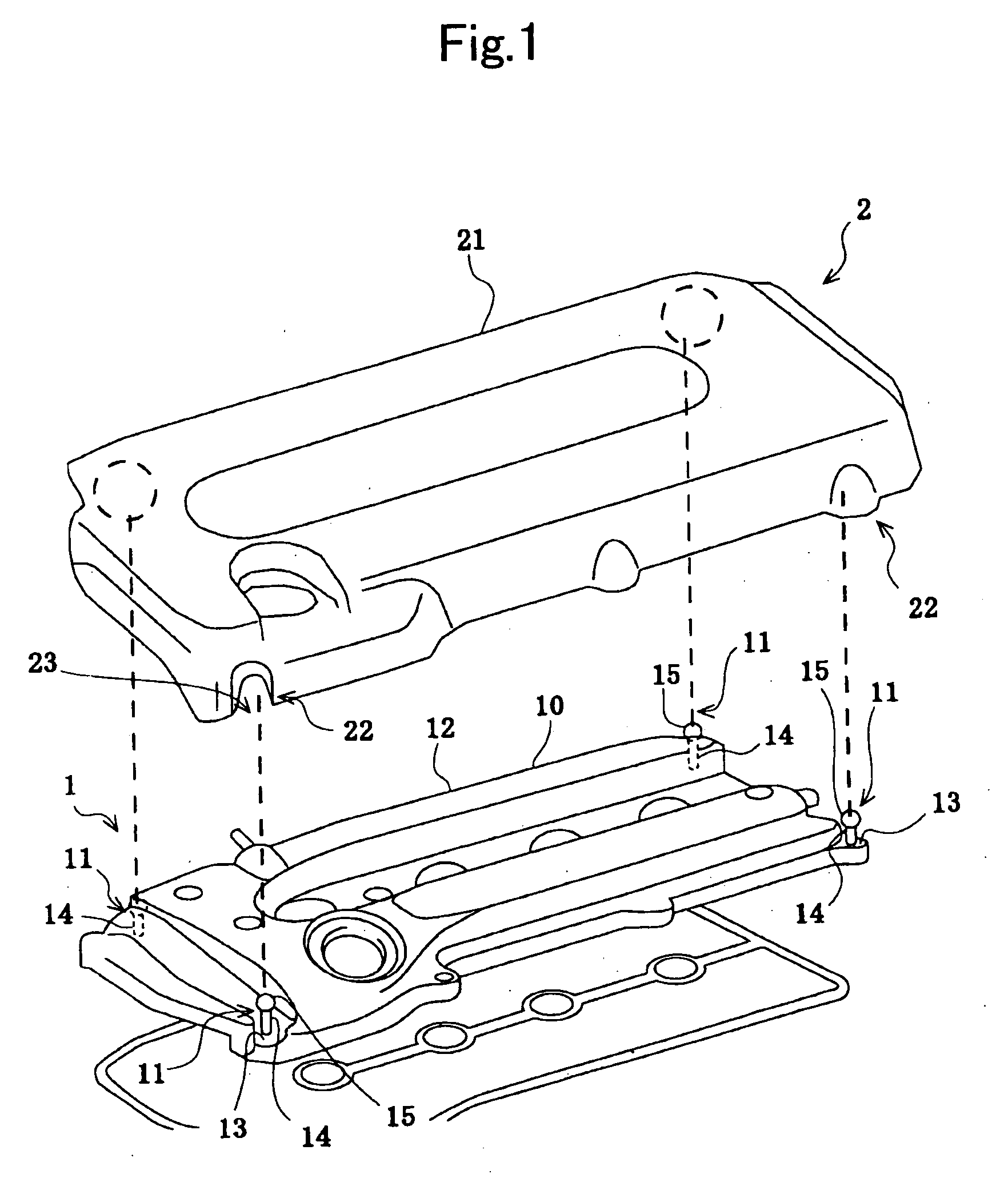
[0044] An engine cover according to Example No. 1 of the present invention comprises a cover body, installation members, which include a leg and a head, respectively, and installed members, which include a framed member and an elastic member, respectively. FIG. 1 is an exploded perspective diagram for schematically illustrating the engine cover according to Example No. 1. FIGS. 2 and 3 are cross-sectional diagrams for schematically illustrating the engine cover according to Example No. 1, respectively.

[0045] The engine cover according to Example No. 1 of the present invention comprises a cover body 2, installation members 11, and installed members 22. The installation members 11 are disposed on a cylinder head cover 10, one of the component parts of an engine 1. The cylinder head cover 10 comprises a primary portion 12, and peripheral portions 13. The primary portion 12 of the cylinder head cover 10 is formed as an inverted trough shape, whose top surface swells upward...

example no.2

Example No. 2

[0055] Except that an engine cover according to Example No. 2 of the present invention comprises the installed members 22 whose elastic members 25's second holes 27 have a different inside diameter D2 from the inside diameter D2 of those in the engine cover according to Example No. 1, the engine cover according to Example No. 2 comprises the same constituent parts as those of the engine cover according to Example No. 1. Specifically, in the engine cover according to Example No. 2, the second holes 27 had an inside diameter D2 of φ 5 mm; and accordingly the ratio of the inside diameter D2 of the second holes 27 to the outside diameter D1 of the heads 15 was D2 / D1=0.625.


PUM

PropertyMeasurementUnit
diameter D1aaaaaaaaaa
diameter D3aaaaaaaaaa
axial overall length L1aaaaaaaaaa

Abstract

An engine cover includes an installation member, a cover body, and an installed member. The installation member is disposed on an engine. One of the installation member and the installed member includes a leg, and a head, and the other one of them includes a framed member, and an elastic member. The elastic member includes a first hole, a second hole, and a diametrically-enlarged intermediate hole. The head engages with the diametrically-enlarged intermediate hole. Moreover, the head is disposed movably toward the second hole when a downward load is applied to the cover body, thereby bringing the cover body closer to the engine.

Description

BACKGROUND OF THE INVENTION [0001] 1. Field of the Invention [0002] The present invention relates to an engine cover for covering engines. In particular, it relates to a construction for installing an engine cover to engines. [0003] 2. Description of the Related Art [0004] In the engine rooms of recent automobiles, it is general to dispose an engine cover above the engine and below the bonnet hood. The engine cover has a function of shielding noises emitted out from the engine (or transmission sounds) as well as a function of upgrading the decorativeness in the engine room by shielding the engine visually. [0005] In general, an engine cover is installed to the cylinder head cover of an engine. In this instance, the engine cover is usually installed to the cylinder head cover by means of fastening with screw bolts, for example, as disclosed in Japanese Unexamined Patent Publication (KOKAI) No. 2001-98,954. An engine cover disclosed in the publication is provided with through holes. A...

Claims


Application Information

Patent Timeline
Patent Type & Authority Applications(United States)
IPC IPC(8): F02B77/00F02M35/02
CPCF02F7/006F02F7/008F02M35/10137F02M35/10321F02M35/161
Inventor NONOGAKI, HARUHIKOMAEDA, ITSURO
Owner TOYODA GOSEI CO LTD
Learn More