Isolated switching power supply

Active Publication Date: 2015-03-19
FUJI ELECTRIC CO LTD
View PDF5 Cites 5 Cited by
  • Summary
  • Abstract
  • Description
  • Claims
  • Application Information

AI Technical Summary

Benefits of technology

The patent describes an isolated switching power supply that can change between a normal operation mode and a low power standby mode without needing an external control signal. This is achieved by monitoring the output voltage and making changes accordingly. This eliminates the need for a photo-coupler and simplifies the construction of the power supply. The switch can detect changes in the load and make the appropriate adjustments. This results in a more reliable and efficient power supply.

Problems solved by technology

However, the newly required photo-coupler cancels the advantage of the isolated switching power supply of a primary side feedback type, which can reduce the number of components.

Method used


Image

  • Isolated switching power supply
  • Isolated switching power supply
  • Isolated switching power supply

Examples


first embodiment

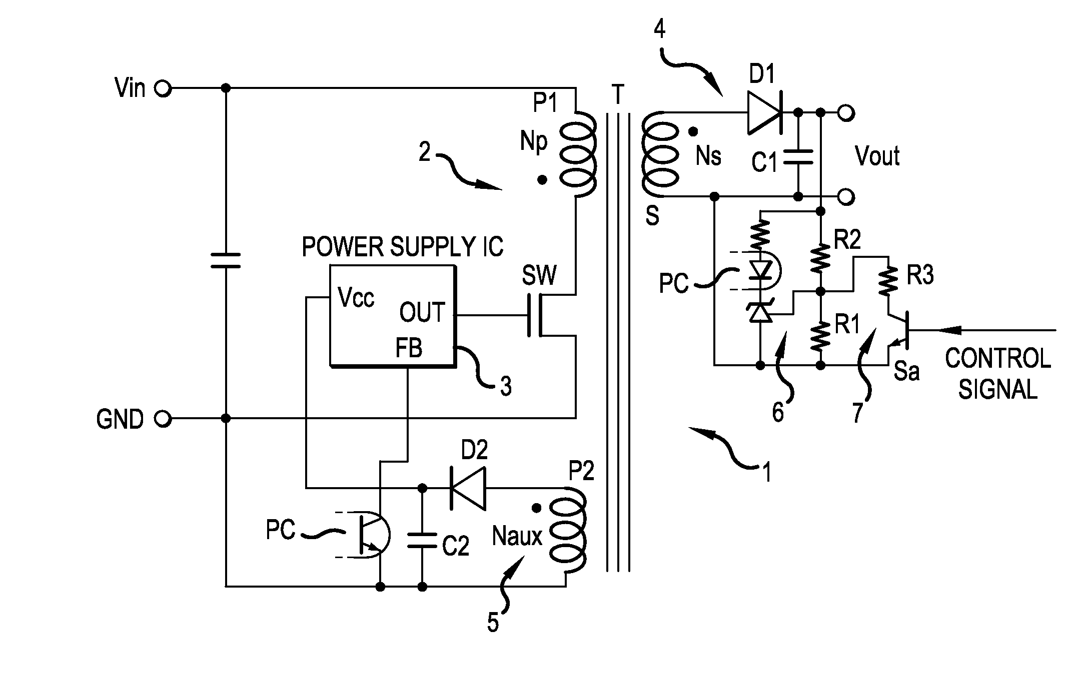
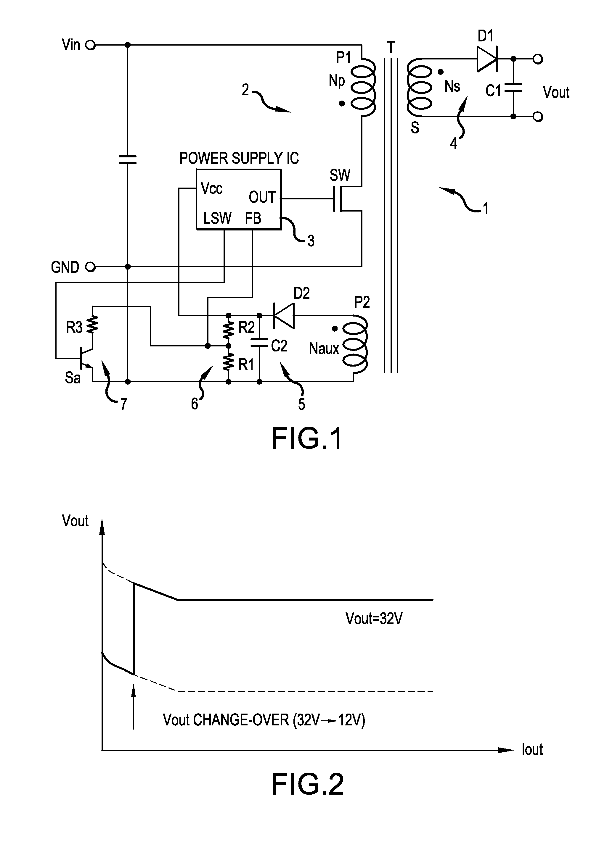
[0029]FIG. 1 is a schematic circuit diagram of a part of an isolated switching power supply 1 of a primary side feedback type according to the present invention. This isolated switching power supply 1 has a basic construction similar to the isolated switching power supply shown in FIG. 6 and thus, is given the same symbols for the similar components and repeated description is omitted.

[0030]The isolated switching power supply according to the first embodiment features a construction in which an operation control signal is given from the control circuit 3 to the switch Sa of the output voltage controller (also referred to herein as a “controlling means”) 7. Upon turning ON the switch Sa, the auxiliary resistor R3 coupled in series with the switch Sa is connected in parallel to the resistor R1 of the output voltage detecting circuit 6, thereby changing the level of the output monitoring voltage.

[0031]The operation control signal given to the switch Sa from the LSW terminal of the cont...

third embodiment

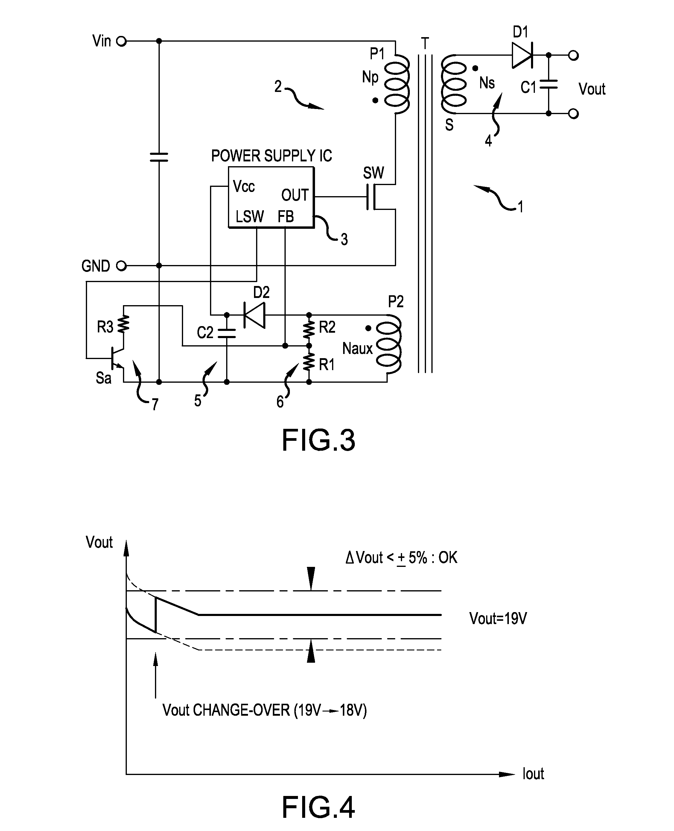
[0042]FIG. 4 shows an example of an output characteristic of the isolated switching power supply according to the present invention. The increase of the output voltage Vout can be controlled to be restricted in a light load period in place of setting a low power standby mode as described previously. When the switching frequency of the switching element SW is controlled corresponding to the magnitude of the load, the stabilizing control for the output voltage Vout is impaired caused by the switching characteristics of the switching element SW, gradually increasing the output voltage Vout.

[0043]When the increase of the output voltage Vout occurs, the level of the output monitoring voltage is changed using the operation control signal to decrease the control target value of the output voltage Vout. Consequently as shown in FIG. 4, the actual output voltage Vout of the isolated switching power supply can be controlled to be confined within a certain error range ΔVout irrespective of the...


PUM


Abstract

An isolated switching power supply can include a switching element connected to an input power supply, a control circuit that ON / OFF-drives the switching element and generates an AC power in a secondary winding and in an auxiliary winding of the isolation transformer, an output circuit that rectifies the AC power generated in the on a secondary winding of the isolation transformer and outputs the rectified power, an internal power supply circuit that generates a driving power supply voltage for the control circuit from the AC power generated in the auxiliary winding, an output voltage detecting circuit that feeds back an output monitoring voltage obtained from the driving power supply voltage to the control circuit to control the ON / OFF driving of the switching element by the control circuit and an output voltage controller that changes a level of the output monitoring voltage obtained from the driving power supply voltage.

Description

CROSS-REFERENCE TO RELATED APPLICATION[0001]This application is based on, and claims priority to, Japanese Patent Application No. 2013-193049, filed on Sep. 18, 2013, the contents of which are incorporated herein by reference.BACKGROUND OF THE INVENTION[0002]1. Field of the Invention[0003]Embodiments of the invention relate to isolated switching power supplies.[0004]2. Description of the Related Art[0005]FIG. 5 shows an example of isolated switching power supply having a main circuit 2 including a primary winding P1 of an isolation transformer T connected to an input power supply Vin and a switching element SW connected to the primary winding P1. The switching element SW is composed of an IGBT or a power MOSFET, for example. The switching element SW is ON / OFF driven by a control circuit 3 constructed as a power supply IC, for example, to generate an AC power in a secondary winding S and an auxiliary winding P2 of the isolation transformer T.[0006]The AC power generated in the second...

Claims


Application Information

Patent Timeline
IPC IPC(8): H02M3/335H02M1/00
CPCH02M2001/0032H02M3/33507H02M3/33523H02M1/0025H02M1/0032H02M1/0035Y02B70/10
Inventor NISHIJIMA, KENICHI
Owner FUJI ELECTRIC CO LTD
Why Eureka
Try Eureka