Drive device of an elevator

a technology of drive device and elevator, which is applied in the direction of elevators, building lifts, transportation and packaging, etc., can solve the problems of unreliable contactors, mechanical components, and impaired safety in the elevator system, so as to improve the efficiency ratio of the elevator system, prevent the effect of dc bus power supply to the elevator motor

Active Publication Date: 2015-03-19
KONE CORP
View PDF14 Cites 9 Cited by
  • Summary
  • Abstract
  • Description
  • Claims
  • Application Information

AI Technical Summary

Benefits of technology

[0010]In a preferred embodiment of the invention the aforementioned brake controller is connected to the DC bus, and the brake controller comprises the aforementioned switch for supplying power from the DC bus to the control coil of the electromagnetic brake. Consequently, also the energy returning to the DC bus in connection with braking of the elevator motor can be utilized in the brake control, which improves the efficiency ratio of the drive device of an elevator. In addition, the main circuit of the drive device of an elevator is simplified when a separate electricity supply for the brake controller does not need to be arranged in the drive device.
[0036]In the most preferred embodiment of the invention the safety signal is connected when a direct-voltage signal travels via the contact of the safety relay that is in the electronic supervision unit to the input circuit that is in the drive device, and the safety signal is disconnected when the passage of the direct-voltage signal to the drive device is disconnected by controlling the aforementioned contact of the safety relay open. Consequently, also detachment or cutting of the conductor of the safety signal results in disconnection of the safety signal, preventing the operation of the elevator system in a fail-safe manner. Also a transistor can be used in the electronic supervision unit instead of a safety relay for disconnecting the safety signal, preferably two or more transistors connected in series with each other, in which case a short-circuit of one transistor still does not prevent disconnection of the safety signal. An advantage in using a transistor is that with transistors the safety signal can, if necessary, be disconnected for a very short time, e.g. for a period of approx. 1 millisecond, in which case a short break can be filtered out of the safety signal in the input circuit of the drive device without it having an effect on the operation of the safety logic of the drive device. Consequently, the breaking capacity of the transistors can be monitored regularly, and even during a run with the elevator, by producing in the electronic supervision unit short breaks in the safety signal and by measuring the breaking capacity of the transistors in connection with a disconnection of the safety signal.

Problems solved by technology

Opening of a safety switch indicates that the safety of the elevator system has been jeopardized.
Contactors, as mechanical components, are unreliable because they only withstand a certain number of current disconnections.
A failure of a contactor might consequently result in impaired safety in the elevator system.
As components, contactors are of large size, for which reason devices containing contactors also become large.
On the other hand, it is a general aim to utilize built space as efficiently as possible, in which case the disposal of large-sized elevator components containing contactors may cause problems.

Method used


Image

  • Drive device of an elevator
  • Drive device of an elevator
  • Drive device of an elevator

Examples


Embodiment Construction

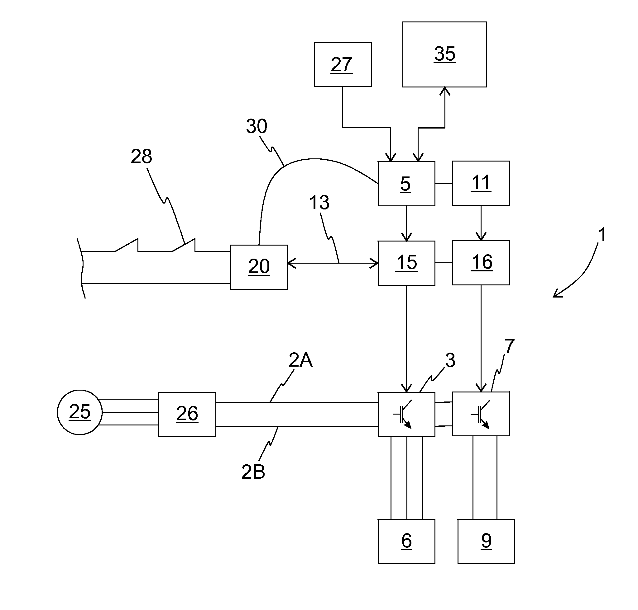
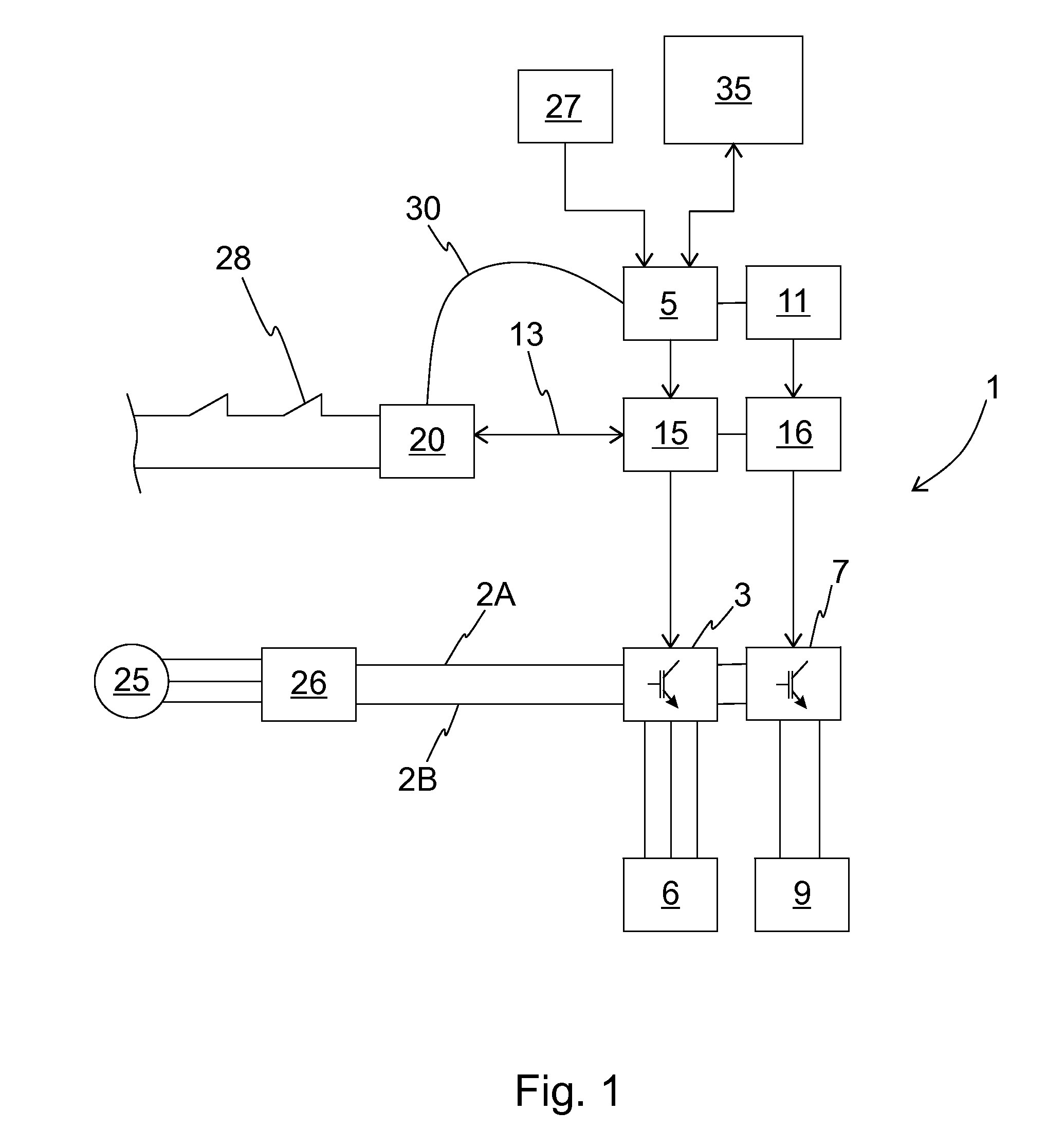
[0046]FIG. 1 presents as a block diagram a safety arrangement in an elevator system, in which an elevator car (not in figure) is driven in an elevator hoistway (not in figure) with the hoisting machine of the elevator via rope friction or belt friction. The speed of the elevator car is adjusted to be according to the target value for the speed of the elevator car, i.e. the speed reference, calculated by the elevator control unit 35. The speed reference is formed in such a way that the elevator car can transfer passengers from one floor to another on the basis of elevator calls given by elevator passengers.

[0047]The elevator car is connected to the counterweight with ropes or with a belt traveling via the traction sheave of the hoisting machine. Various roping solutions known in the art can be used in an elevator system, and they are not presented in more detail in this context. The hoisting machine also comprises an elevator motor, which is an electric motor 6, with which the elevat...


PUM


Abstract

A drive device of an elevator includes a DC bus, a motor bridge connected to the DC bus for the electricity supply of the elevator motor, which motor bridge includes high-side and low-side switches for supplying electric power from the DC bus to the elevator motor when driving with the elevator motor, and also from the elevator motor to the DC bus when braking with the elevator motor, a control circuit of the motor bridge, with which control circuit the operation of the motor bridge is controlled by producing control pulses in the control poles of the high-side and low-side switches of the motor bridge, a brake controller, which comprises a switch for supplying electric power to the control coil of an electromagnetic brake, a brake control circuit, with which the operation of the brake controller is controlled by producing control pulses in the control pole of the switch of the brake controller, an input circuit for the safety signal to be disconnected / connected from outside the drive device, drive prevention logic, which is connected to the input circuit and is configured to prevent the passage of control pulses to the control poles of the high-side and / or low-side switches of the motor bridge when the safety signal is disconnected, and also brake drop-out logic, which is connected to the input circuit and is configured to prevent passage of the control pulses to the control pole of the switch of the brake controller when the safety signal is disconnected.

Description

FIELD OF THE INVENTION[0001]The invention relates to the safety systems of the drive devices of an elevator.BACKGROUND OF THE INVENTION[0002]In an elevator system, there must be a safety system according to safety regulations, by the aid of which safety system the operation of the elevator system can be stopped e.g. as a consequence of a defect or of an operating error. The aforementioned safety system comprises a safety circuit, which comprises safety switches in series, which switches measure the safety of the system. Opening of a safety switch indicates that the safety of the elevator system has been jeopardized. In this case operation of the elevator system is interrupted and the elevator system is brought into a safe state by disconnecting with contactors the power supply from the electricity network to the elevator motor. In addition, the machinery brakes are activated by disconnecting with a contactor the current supply to the electromagnet of the machinery brake.[0003]Contac...

Claims


Application Information

Patent Timeline
Patent Type & Authority Applications(United States)
IPC IPC(8): B66B5/02
CPCB66B5/02B66B1/32B66B5/025B66B5/00B66B5/0031B66B5/06B66B1/30B66B2201/00B66B13/22B66B1/308
Inventor KATTAINEN, ARIRAASSINA, PASISAARIKOSKI, TAPIOSTOLT, LAURINAKARI, ARTOKALLIONIEMI, ANTTI
Owner KONE CORP
Why Eureka
Try Eureka