
Apparatus for Operating Syringe Piston

a technology of syringe and syringe, which is applied in the direction of medical syringes, automatic syringes, infusion syringes, etc., can solve the problems of difficult to accurately inject a precise amount of medical cement into the tissue of the patient, difficult to manually apply constant pressure to the piston, and difficult to accurately calibrate the amount of injecting medicine. , to achieve the effect of easy turning the handle and accurately calibrating the amount of medicin

Inactive Publication Date: 2015-03-12
KIM SEOK JUNG +5
View PDF2 Cites 2 Cited by
  • Summary
  • Abstract
  • Description
  • Claims
  • Application Information

AI Technical Summary

Benefits of technology

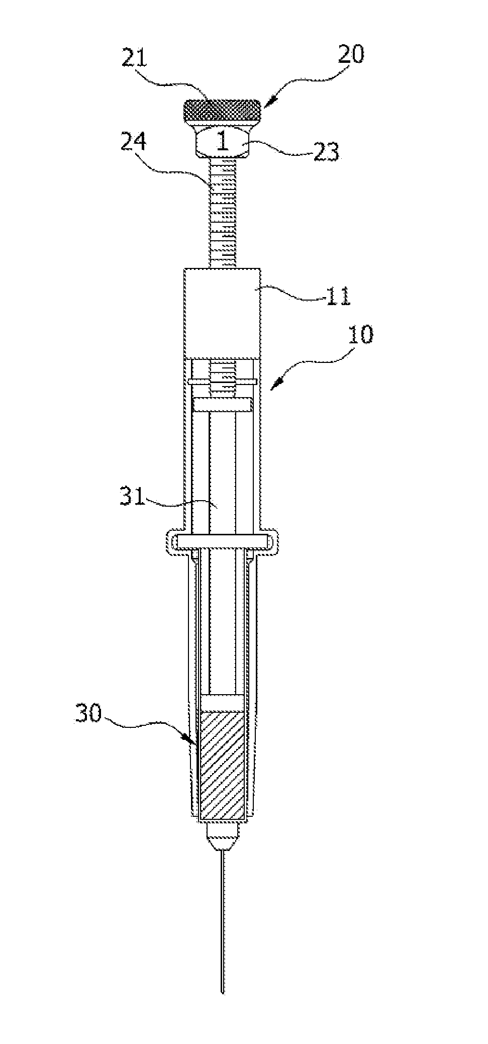
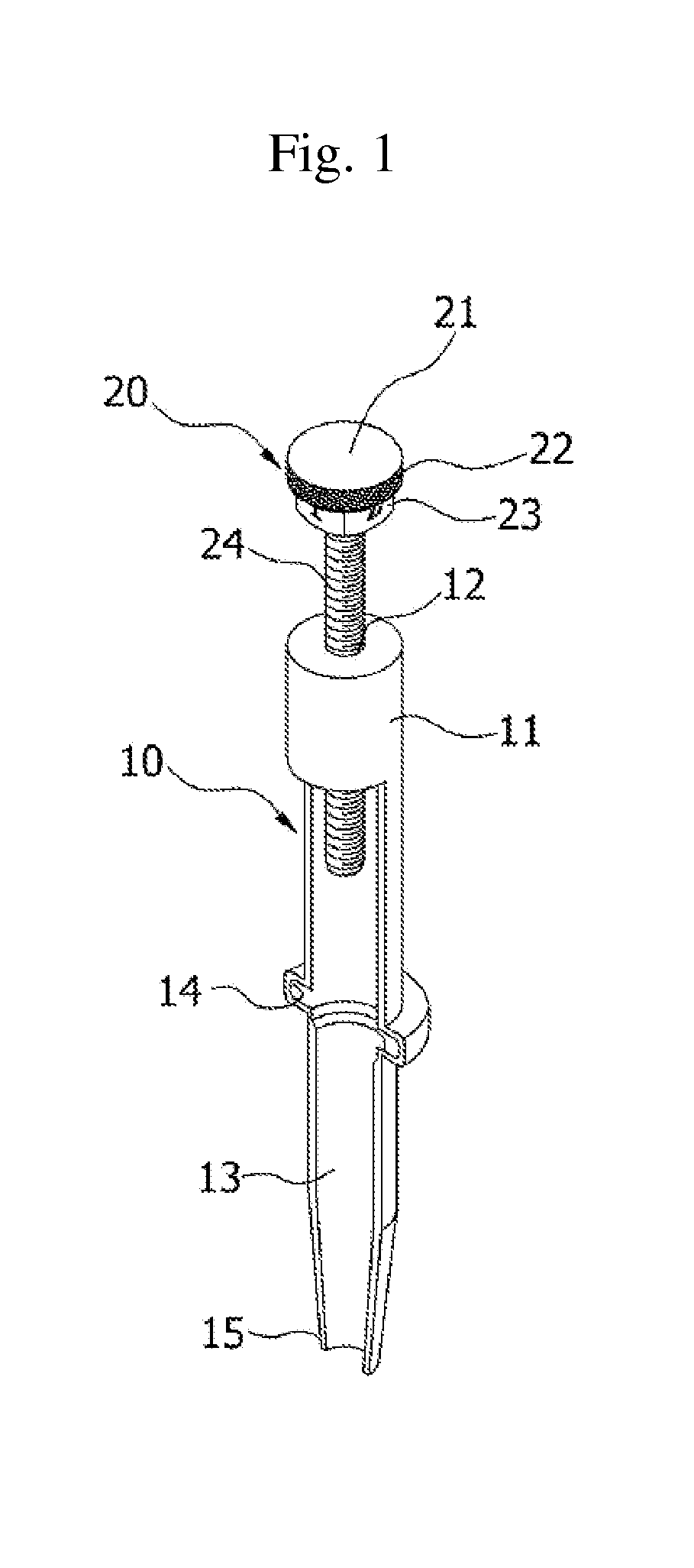
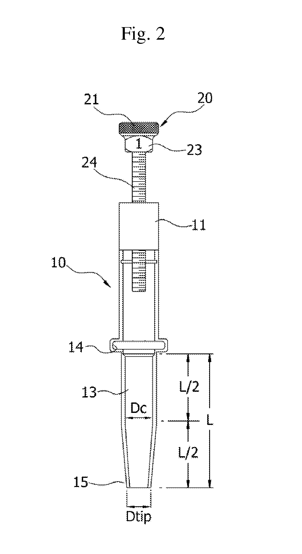
The present invention provides an apparatus for operating a syringe piston which can accurately inject a predetermined amount of medical cement into a human body. The apparatus includes a syringe piston press unit with a handle and an anti-slip knob section for easy handling. The handle has a polygonal section with calibrated figures for accurately measuring the amount of injecting medicine. The inner diameter of the tube section is gradually reduced for smooth extrusion of the medical cement. The apparatus can significantly improve medical technique, procedure quality and reliability, and provide consumers with high satisfaction and a good impression.

Problems solved by technology

However, the conventional syringe is rarely used for this type of procedure due to the following reason: when the medical cement is injected into the tissue of the patient, a relatively great pressure must be applied to the piston due to the physical properties of the medical cement.
However, it is very difficult to manually apply a constant pressure to the piston, thus it is also very difficult to inject a precise amount of medical cement into the tissue of the patient.

Method used


Image

  • Apparatus for Operating Syringe Piston
  • Apparatus for Operating Syringe Piston
  • Apparatus for Operating Syringe Piston

Examples


Embodiment Construction

[0023]Hereinafter, an apparatus for operating a syringe piston according to a preferred embodiment of the present invention will be described with reference to FIGS. 1 to 7.

[0024]In the following description of the present invention, the explanations of the known functions and configurations, which are incorporated with the subject matter of the present invention, will be omitted.

[0025]In addition, the terms used in the following description of the present invention are prepared in view of functions thereof, so they will be changed depending on the intention of manufacturers or custom. Thus, definition of the terms must be determined based on the whole content of the specification.

[0026]The present invention provides an apparatus for operating a syringe, which is comprised of a syringe mounting section (10) for securely holding a syringe (30) and a piston press unit (20) for operating a syringe piston (31) with a constant pressure. The syringe (30) filled with medical cement is plac...


PUM


Abstract

An apparatus for operating a syringe has developed comprising that: an upper semi-cylindrical tube section, semi-circular groove shaped locking slot and lower semi-cylindrical tube section. The upper semi-cylindrical tube section is integrally formed an upper head part with a threaded hole for axial movement. The lower semi-cylindrical tube section forms a top portion, intermediate portion and end portion. A diameter (Dc) at the intermediate portion is larger than the diameter (Dtip) at end portion, which is gradually reduced from intermediate to end portion. The length of tapered portion is same as that of the constant diameter portion. A tip portion has formed an opened semi-circular shape to simply overlap the syringe over the syringe mounting device for easily snapping-in and out. The syringe piston moves downward with no reverse action when the piston press unit is rotated, so that it is possible to inject the precise amount of medical to a patient with constant pressure.

Description

[0001]This application is a Continuation in Part of patent application Ser. No. 12 / 226,316, which is filed Oct. 15, 2008 and claims the priority of Korean Patent Application No. 10-2006-0036206, which is filed Apr. 21, 2006 and entire disclosure of which is herewith incorporated by reference.BACKGROUND OF THE INVENTION[0002]1. Field of the Invention[0003]The present invention relates to an apparatus for operating a syringe piston. More particularly, it is comprised of a syringe mounting section for holding a medicine filled syringe and a piston press unit for operating a syringe piston without reverse action while the piston is depressing, so that the medicine contained in the syringe can be injected into a patient's body with constant pressure, ensuring that an accurate amount of medicine is delivered.[0004]2. Related Prior Art[0005]As generally known in the art, a syringe is a device for injecting a liquid medicine into a tissue of a living body. The syringe mainly includes a need...

Claims


Application Information

Patent Timeline
Patent Type & Authority Applications(United States)
IPC IPC(8): A61M5/315A61M5/31
CPCA61M5/31A61M5/31511A61M5/484A61M5/20A61M5/31565A61M2005/2026
Inventor KIM, SEOK-JUNGCHANG, CHEONG-HOJANG, JAE-DEOGPARK, HYUN-SHINLEE, SAE-BOMBYUN, KYOUNG-PHIL
Owner KIM SEOK JUNG
Learn More