Sheet storage box

a box and box body technology, applied in the direction of flat article dispensing, thin material handling, packaging, etc., can solve the problems of tissue paper can easily fall into storage boxes by getting caught, paper falling into storage boxes, etc., to achieve the effect of eliminating drawbacks and easy raising of sheets

Active Publication Date: 2015-03-12
FUJIMOTO HIROMICHI
View PDF35 Cites 11 Cited by
  • Summary
  • Abstract
  • Description
  • Claims
  • Application Information

AI Technical Summary

Benefits of technology

[0086]According to the operation as mentioned in the preceding paragraph 0070, the curved opening rims become the same kind of smooth convex shape and as there is no retroflexion of the depression in the projected portion used to slide the sheet, the projected opening rim and sheet come in contact with each other and the resistance can be decreased. There does not exist a large gap between the projections and the depressions of the opening rims opposite the projection, and therefore, the movement of the sheet can be suppressed at the time of pulling out the sheet. The sheets can be fixed smoothly by reducing the space pushed by the opening.
[0091]According to the effect of the preceding paragraph 0070 mentioned above, the sheet can be pulled out smoothly and it can be fixed in such a way that it is difficult for the sheet to fall into the storage box.
[0093]According to the effect of the preceding paragraph 0072 mentioned above, the movement of the sheet can be suppressed as the sheets are prevented from being guided toward an opening not intended.
[0094]According to the effect of the preceding paragraph 0073 mentioned above, as the small folding line nearly similar to the shape of the projection can be put into the sheet by using the smooth projections on both sides and a small subordinate projection between them, the sheet can be raised easily.
[0095]According to the effect of the preceding paragraph 0074 mentioned above, as the shape of both ends of the opening is made into the shape including the concave curve shape, the drawback is eliminated that, if both ends of the opening are an acute angle, the sheet gets stuck and the movement of the sheet is hindered, and the sheet can be caught smoothly in the depression due to the restoring force of the sheet itself.

Problems solved by technology

Furthermore, conventionally there are various methods of folding the tissue paper such as a one time folding method or a two time folding method, and the size of each folded side of the tissue paper and the position of the folded line is not always uniform.
Furthermore, if a sharp projection exists at the position near (a-a′), it easily gets caught on a joint line of a newly appearing tissue paper and while pulling out the tissue paper, since the next appearing tissue paper lies over the pulling out tissue paper, if the joint line of the next tissue paper lies on the portion of the pulling out tissue paper where the largest force is applied, the tissue paper can easily fall into the storage box by getting caught.
However, according to a method of fixing or removing the tissue paper illustrated in FIG. 7, as the protruding projection is small with a very sharp curve forming the projection and a position held at the time of pulling out the tissue paper is not always at the center, if the tissue paper is held above the projection, there is a possibility of the paper falling into the storage box due to the joint line of the next appearing tissue paper getting caught on the portion where the projection is overlapped with the portion where the strength is concentrated at the narrow range of the tissue paper.
At the time of removing the sheet, since the paper is drawn by inserting a finger from either the left or right side hole, it is obviously more difficult to take the paper out, because it is not possible to take the paper out evenly from the right or left, than a case where the center and its surrounding area are drawn, and the opening has to be reduced to some extent to fix the sheet, otherwise it is difficult to remove the tissue paper.
However, according to FIG. 9, the tissue paper is fixed by narrowing the moving range but, similar to the preceding FIG. 8, the opening has a shape having the apex of the projection near its center, and the same problem described above occurs.
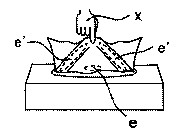
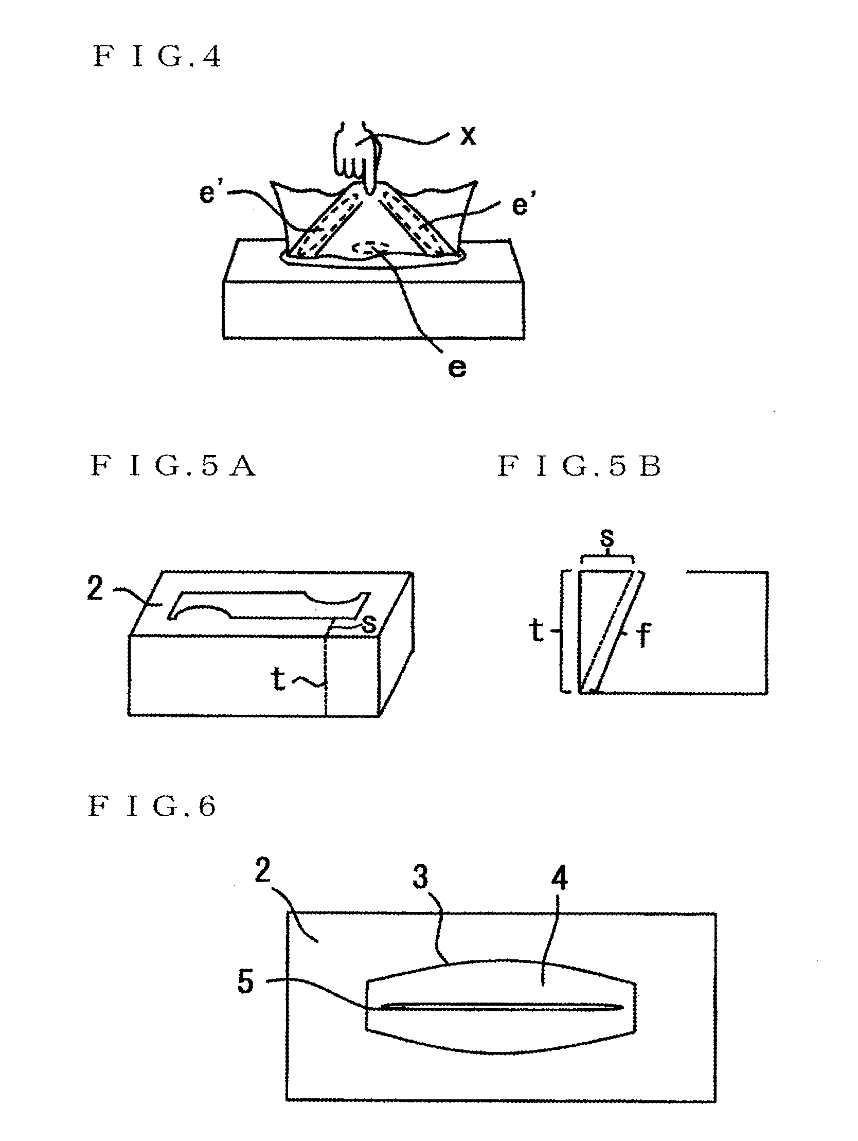
Furthermore, in conventional sheet storage boxes, the projection is raised by inserting the folded line near the bottom of the projection opposite the apex of the projection but, if the projection is raised, the resistance at the time of removing a sheet is reduced and when a sheet falls into the storage box, it takes quite a bit of effort to pull it out since the projection abuts on the finger and if the shape of the projection is complicated, it requires even greater effort.
However, the form mentioned in Japanese Published Unexamined Patent Application No. 2008-137686 has drawbacks mentioned in the preceding paragraph 0047 hereof wherein, the opening has only single direction inclination with respect to the front side or back side of the sheet and the opening needs to be extremely inclined to reduce the space of the opening.
When the cover made of cloth, etc., is used to cover the sheet storage box as illustrated in FIG. 16, the central portion of the sheet becomes difficult to remove from the opening and the sheets again slide and fall into the storage box due to the poor method of removing the sheets.
The main method for fixing the sheets is determined by partially pushing the sheet by the projections and since the four projections are not formed by convex curves, tissue paper cannot be fixed or moved without rendering too much resistance to the tissue paper.
However, if the sheet is inserted too much into the slit depending on the shape, the sheet is torn at the time of removing and the space for removing the sheets become too large if a slit is not used and this resulted in a drawback similar to the drawback mentioned in paragraph 0047 hereof.
There are two apexes of projections on one side rim and one apex on the opposite side rim and if the flap does not work properly, the tissue paper may get caught near the apex of the projection.
However, the flap of the opening is like a covering lid and the flap may get in the way of fingers at the time of removing tissue paper in the storage box which makes it difficult to remove the tissue paper.
Furthermore, the central projection may hinder movement of the tissue paper.
In other words, the opening is such that, at the time of beginning to pull out the sheets from the storage box, the next sheet is likely to get caught as the apex of the projection is present near the portion to which force is likely to be applied on the sheet and since the wide finger tip insertion space cannot be provided in the center of the opening as it is not point symmetric, it requires quite a bit of effort to insert fingers in the storage box from the opening when the sheet falls into the storage box.
In other words, if there are two pairs of projections opposite each other with acute angles, the shape similar to or the same as that mentioned in the preceding FIG. 7 is formed and the same problems as that mentioned in the preceding FIG. 7 occur.
As mentioned above, although pasting the sheet-fixing sheet on the sheet-removing opening is suitable for removing the sheets, it is wasteful from the point of view of resources.
As mentioned above, when the sheet-fixing sheet is not pasted on the opening of the sheet storage box, the fixing of sheets becomes weaker as the opening itself becomes larger due to the excessively wide rim of the opening and when the rims of the opening are made too close, the rim of the opening partially becomes smaller and the resistance to remove the sheets becomes too large.

Method used


Image

  • Sheet storage box
  • Sheet storage box
  • Sheet storage box

Examples


examples

[0122]FIG. 34 is a diagram illustrating an example of a top lid provided on the sheet-removing opening of the present invention wherein, (27) is the top lid which can be detached from the vicinity of to the center of the opening by dividing into half by using a perforated line, (28) is a thin portion of the top lid and (29) is a portion of the top lid with a perforated line wherein a hole can be made by inserting a finger.

[0123]The portion of (28) wherein, the top lid has become thin is made easier to move away from the surrounding perforated line by elongating the cut portion of the perforated line of (15′) and the top lid is made easier to move away by completely cutting the tip portion of the acute angle portion.

[0124]Furthermore, double perforated lines may be provided. There is no limit on types such as shape, interval, and number of perforated lines.

[0125]FIG. 35 shows an example of the sides which forms the storage box that can be used in the present invention wherein, (A) is...


PUM


Abstract

Conventional sheet storage boxes have problems that the sheet storage box with a sheet-fixing sheet pasted on the sheet-removing opening is wasteful from the point of view of resources and that, in the case of the sheet storage box without the sheet-fixing sheet pasted on the opening, the fixing of sheet becomes weaker as the opening itself becomes larger due to the excessively wide rim of the opening and when the rims of the opening are made too close, the rim of the opening partially becomes smaller and the resistance to remove the sheets becomes too large. To solve the above problems of the conventional sheet storage boxes, the present invention provides a sheet-removing opening by effectively forming the portion to remove the sheet easily from the opening and the portion to easily catch the sheet wherein, the shape of the rims of the opening of the sheet storage box designed to remove the sheet is formed in such a way that the movement of the sheet is reduced by adequately reducing the spatial area of the opening and the rims of the opening are converted to convex shape smooth curves to smoothly slide the sheet.

Description

BACKGROUND OF THE INVENTION[0001]The present invention relates to a box-shaped sheet storage container to store any kind of dry sheet such as tissue paper, kitchen paper, cooking sheets and vinyl bags by folding back and overlapping each sheet one above the other one by one.[0002]A conventional removing opening of a box-shaped tissue-paper storage box, made of paper and the like, includes: that in which a tissue-paper fixing sheet which is formed of a high polymer such as a plastic and which has a cut for opening at the center is pasted on the opening of the sheet storage box; that which has an excessive gap at the center of the opening and which is line symmetric or point symmetric, without the above-described fixing sheet being pasted at a sheet-removing opening; and that in which projections forming the rims of the opening are protruded to substantially the center of the opening and which prevents smooth removal of the tissue paper.[0003]Furthermore, normally, the tissue paper is...

Claims


Application Information

Patent Timeline
Patent Type & Authority Applications(United States)
IPC IPC(8): B65D83/08
CPCB65D83/0805A47K10/421B65D83/0894
Inventor FUJIMOTO, HIROMICHI
Owner FUJIMOTO HIROMICHI
Why Eureka
Try Eureka