
Drill with depth measurement system

Active Publication Date: 2015-03-05
MCGINLEY ENGINEERED SOLUTIONS
View PDF58 Cites 36 Cited by
  • Summary
  • Abstract
  • Description
  • Claims
  • Application Information

AI Technical Summary

Benefits of technology

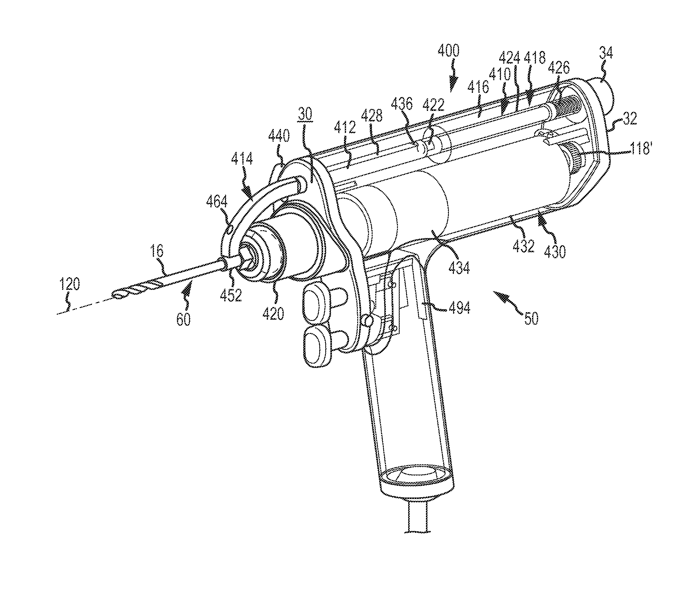
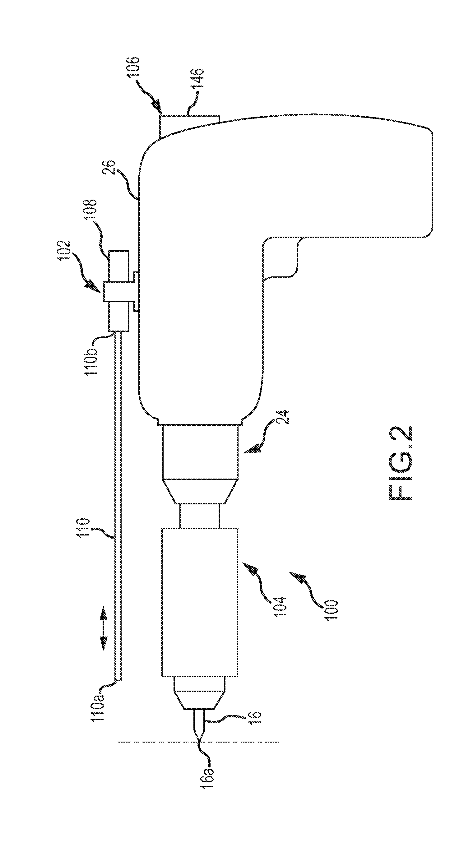
The present disclosure is related to drill bit assemblies, drills, and drilling systems that may be specifically adapted for drill bit penetration measurement. These improvements may increase efficiency, reliability, and accuracy in drill bit penetration measurement systems. The patent text describes features such as drill bit assemblies that may be used in conjunction with a drill to facilitate measurement of a bore created by the drill using a drill bit penetration measurement system without having to remove the drill bit from the bore during operation. The efficiency, accuracy, and ergonomics of drill bit penetration measurement systems may be improved. The patent also describes a system for engaging a drill bit with a displacement sensing arm using an engagement member, such as a post, and a destructible portion that can be degraded during a cleaning or sterilization process. This helps prevent the drill bit from being reused in contradiction of instructions regarding one time use.

Problems solved by technology

Inadequate and inaccurate depth measurement following orthopedic drilling procedures may result in incorrect screw lengths, which can lead to surgical complications.
Furthermore, determining the correct screw length for a bore can be a time consuming procedure which is undesirable when tissue is exposed and potentially subjected to infection.
Improper drilling lengths could lead to device instability, damage to anatomic structures, or device failure.
A possible resulting complication of this procedure is that the surgeon may not precisely “feel” the drill bit pass through the second cortical layer, thereby possibly damaging tissue on the opposite side of the bone.
Another complication may occur if the depth gage is not properly inserted into the hole.
Conservative drilling may result in incomplete drilling requiring multiple passes.
This process consumes a substantial amount of surgical time resulting in a large cost per patient.

Method used


Image

  • Drill with depth measurement system
  • Drill with depth measurement system
  • Drill with depth measurement system

Examples


Embodiment Construction

[0077]Certain terminology is used in the following description for convenience only and is not limiting. The words “right,”“left”, “lower” and “upper” designate directions in the drawings to which reference is made. The words “inwardly” and “outwardly” refer to directions toward and away from, respectively, the geometric center of the drill bit penetration measurement system and designated parts thereof. The terminology includes the words above specifically mentioned, derivatives thereof and words of similar import.

[0078]Additionally, as used in the claims and in the corresponding portion of the specification, the word “a” means “at least one”. Further, unless otherwise defined the word “about” when used in conjunction with a numerical value means a range of values corresponding to the numerical value plus or minus ten percent of the numerical value. Still further, the word “or” has the meaning of a Boolean inclusive “Or”. For example, the phrase “A or B” means “A” alone or “B” alon...


PUM


Abstract

A measurement system and method for determining a depth of penetration of a working portion of a surgical instrument (e.g., a rotating drill bit in a bore). A first sensor outputs a first signal representative of a displacement of the leading edge of the drill bit in the bore. A second sensor outputs a second signal representative of a force applied to the leading edge of the drill bit. A processor outputs a third signal representative of the depth of penetration of the leading edge of the drill bit when the leading edge of the drill bit passes from a first medium having a first density to a second medium having a second density. The third signal is based on the first and second signals.

Description

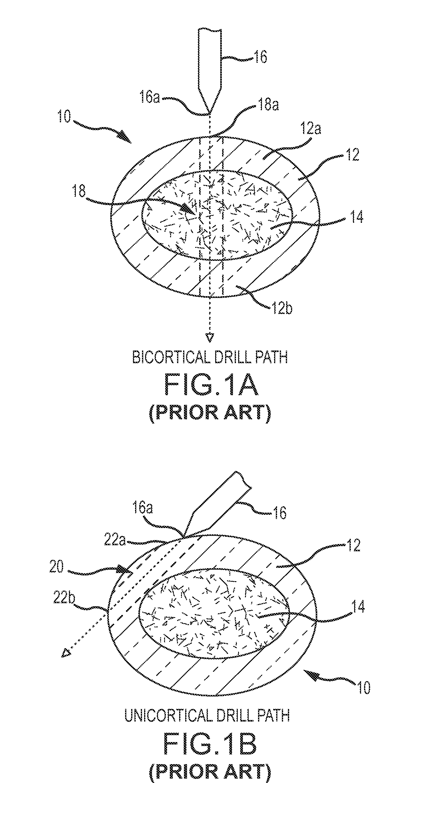
CROSS REFERENCE TO RELATED APPLICATIONS[0001]This application is a continuation of U.S. application Ser. No. 14 / 018,252 filed on Sep. 4, 2013 entitled “DRILL BIT PENETRATION MEASUREMENT SYSTEMS AND METHODS”, the entirety of which is incorporated by reference herein.BACKGROUND[0002]Inadequate and inaccurate depth measurement following orthopedic drilling procedures may result in incorrect screw lengths, which can lead to surgical complications. Furthermore, determining the correct screw length for a bore can be a time consuming procedure which is undesirable when tissue is exposed and potentially subjected to infection.[0003]As shown in FIGS. 1A and 1B, the bony structure of the human anatomy consists mainly of cortical bone 10 having a hard outer cortex 12 and a soft inner medullary layer 14. Following traumatic injury, plate and screw placement is critical for adequate repair of a fractured bone. Improper drilling lengths could lead to device instability, damage to anatomic structu...

Claims


Application Information

Patent Timeline
IPC IPC(8): A61B17/16
CPCA61B17/1615A61B17/162A61B17/1622A61B17/1626A61B90/30A61B2090/062A61B2090/0814A61B17/142A61B17/16A61B17/1628
Inventor MCGINLEY, JOSEPH C.SIMMONS, KEVIN D.PRIVITERA, PETER A.SIM, HENRY K.TANAKA, SHIGERURINALDIS, DAVID J.FAULKNOR, GRAHAM R.LEUGERS, MARTIN A.
Owner MCGINLEY ENGINEERED SOLUTIONS
Learn More