
Thermoelectric sensor for analytes in a gas and related method

a technology of thermoelectric sensor and analytes, applied in the field of apparatus and methods for sensing analytes in fluids, can solve the problems of inability to fully realize the full potential of blood chemistry, laborious, painful blood analysis, etc., and achieve the effect of improving the accuracy of blood tests, and improving the accuracy of blood chemistry

Inactive Publication Date: 2015-03-05
INVOY HLDG INC
View PDF0 Cites 12 Cited by
  • Summary
  • Abstract
  • Description
  • Claims
  • Application Information

AI Technical Summary

Benefits of technology

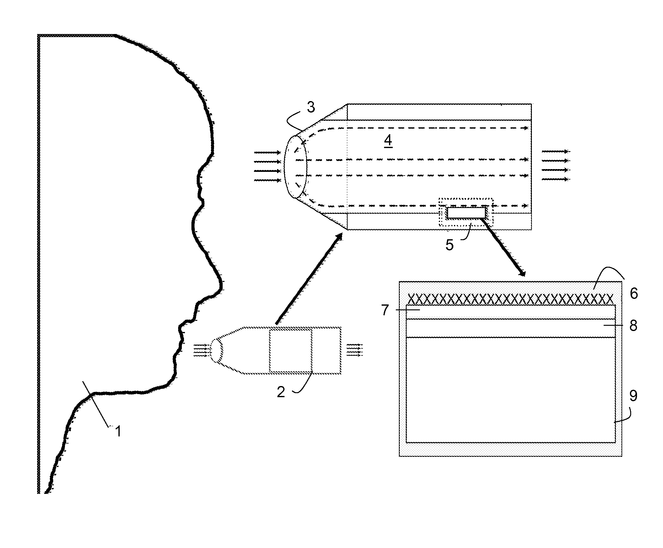
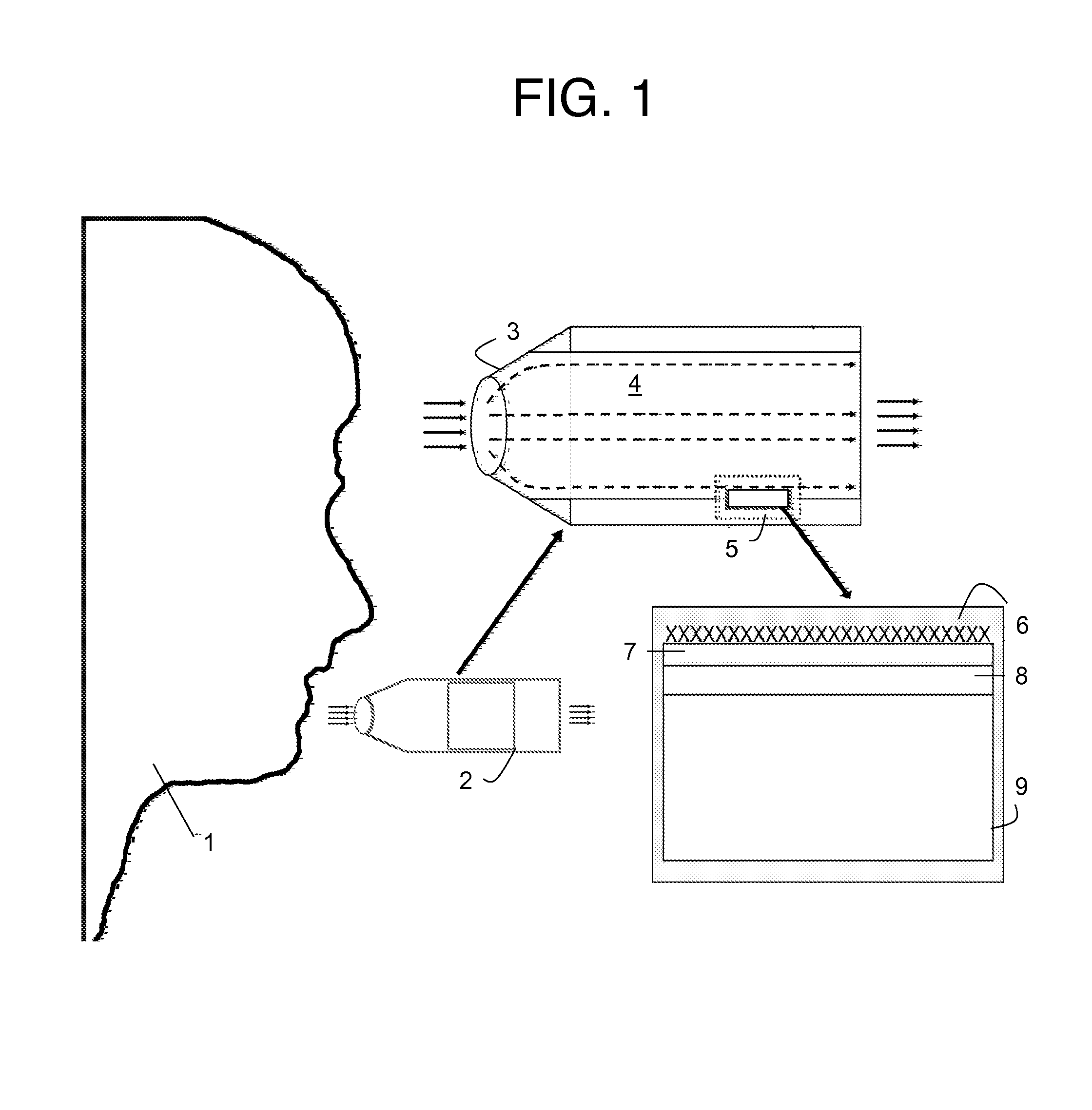
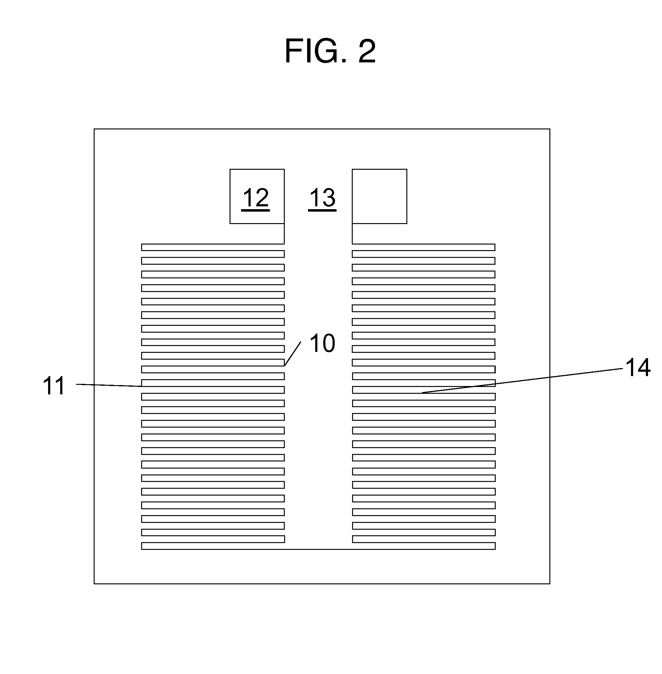
This invention describes systems, devices, and methods for sensing substances in fluids. The technical effects of this invention include the ability to accurately detect and characterize analytes in real-time, with the potential for applications in areas such as medical diagnostics, environmental monitoring, and sports equipment design. The systems use a thermal sensing device and an analyte interactant to measure the temperature change caused by the analyte, which can provide valuable information about the analyte's biological or chemical properties. Additionally, the invention allows for the creation of multiple analyte sensors with different interactants, enhancing the accuracy and reliability of the sensing process.

Problems solved by technology

Historically, breath chemistry has not been very well exploited.
Blood analysis is painful, laborious, relatively expensive and often impractical due to lack of equipment or trained personnel.
While these companies have made home-testing possible, blood tests are still expensive and painful and they require careful disposal and procurement of needed equipment such as needles and collection vessels.
This leads to low patient compliance.
Urine analysis has been criticized as being inaccurate.
Thus, while blood and urine tests can provide information about the physiological state of an individual, they have been relatively unattractive or ineffective for practical application where portability or field or home use is required.
Current systems used to sense an analyte in a gas, such as gas chromatographs and spectroscopy-related devices, are expensive, cumbersome to use, they require skilled operators or technicians, and otherwise typically are not practical for field or home use.
They also tend to be quite expensive.
Precision in detection systems usually comes at substantial cost.
Current highly-accurate detection systems require expensive components such as a crystal, specialized power source, or containment chambers that are highly pH or humidity regulated.
However, the thermopile sensor is limited to measuring a single analyte and only a single reactant is present on the thermopile.

Method used


Image

  • Thermoelectric sensor for analytes in a gas and related method
  • Thermoelectric sensor for analytes in a gas and related method
  • Thermoelectric sensor for analytes in a gas and related method

Examples


example 1

[0276]FIG. 54 shows an embodiment that utilizes a pyroelectric detector 435. The analyte 437 passes through a conduit and interacts with an analyte interactant 432 which is immobilized on a test strip 431. The test strip 431 is passed through the conduit by a mechanism 434, such as a gear, motor, etc, and is guided by a strip director 433. The output of the pyroelectric detector 435 is processed by a signal processing unit 436. As a general matter, the response of thermal sensors is improved by use of thin-film materials. In some instances, if the expected signal is large, the magnitude of the signal is perhaps not an issue. However, the thermal time constant (i.e. the response time) is typically impacted if the heat capacity is high. Accordingly, under most circumstances, it is desirable to employ thin-film materials. With this type of test strip embodiment, to ensure good thermal contact, it is desirable if the test strip is in good mechanical contact with the sensor.

[0277]A speci...

example 2

[0283]In this example, a thermal sensor for oligosaccharide detection is described. Oligosaccharides (“glycans”) are associated with various pathologies, including cancer. These oligosaccharides may be found on the periphery of the cell on the glycocalyx. They also may be found free flowing in blood attached to biomolecules such as proteins. During disease states, the concentration of glycans may increase, the structure of the oligosaccharide may be modified or altered, or neoexpression of certain glycans may occur. Accordingly, measuring glycans can serve as tremendous biomarkers.

[0284]Although sugars are well-known as the “third language of life” (genomics, proteomics, glycomics), because glycoscience is an emerging field, it is important to understand why it is important to measure glycans. First, in some instances, glycans have served as biomarkers where other disease markers have not been identified or are limited (e.g. in multiple sclerosis). Second, many papers have shown tha...


PUM


Abstract

An apparatus is provided for sensing an analyte in a fluid. The apparatus includes a fluid collecting device configured to collect the fluid containing the analyte; a fluid input in fluid communication with the fluid collecting device configured to input the fluid containing the analyte into the fluid collecting device, an analyte interactant in fluid communication with the fluid collecting device, wherein the analyte interactant, when contacted by the analyte, reacts to cause a first change in thermal energy within the fluid collecting device; a modulator that causes a second change in thermal energy; a thermal sensing device comprising at least one pyroelectric device thermally coupled to the fluid collecting device to generate a first signal in response to at least one of the first change in thermal energy and the second change in thermal energy; a control device operatively coupled to the thermal sensing device and the modulator that generates a second signal, wherein the second signal comprises information useful in characterizing the analyte. A related method also is disclosed.

Description

RELATED APPLICATIONS[0001]This is a continuation of U.S. application Ser. No. 11 / 656,338, filed on Jan. 20, 2007, which is a continuation-in-part of U.S. application Ser. No. 11 / 607,829, filed on Dec. 2, 2006, which is a continuation-in-part of U.S. application Ser. No. 11 / 593,144, filed on Nov. 2, 2006, which is a continuation-in-part of U.S. application Ser. No. 11 / 273,625, filed on Nov. 14, 2005, which is a continuation-in-part of U.S. application Ser. No. 10 / 554,801, filed on Oct. 28, 2005, directed to a Thermoelectric Sensor for Analytes in a Gas, which claims priority based on PCT / US2004 / 13364, filed on Apr. 28, 2004, which claims priority to Application No. 60 / 465,949, filed on Apr. 28, 2003, all of which are hereby incorporated by reference in their entireties.FIELD[0002]The invention relates generally to apparatus and methods for sensing analytes in a fluid, such as a liquid or a gas. A preferred example involves the sensing of one or more analytes in air or a gas expired b...

Claims


Application Information

Patent Timeline
Patent Type & Authority Applications(United States)
IPC IPC(8): G01N33/64G01N33/98G01N33/497
CPCG01N33/64G01N33/497G01N2800/042G01N2033/4975G01N33/98A61B5/097G01N25/4813G01N25/4873Y10T436/172307Y10T436/175383Y10T436/196666Y10T436/200833Y10T436/202499Y10T436/203332Y10T436/204165Y10T436/212Y10T436/214G01N33/4972A61B5/082A61B2560/0406A61B2562/0276G01N31/22G01N33/50G01N2800/044G01N15/06G01N2015/0046G01N15/01G01N33/4975G01N27/26G01N25/20G01N25/00G01D1/06G01N15/0205G01N21/0332G01N21/3504G01N21/783G01N21/8483G01N31/224G01N33/6893G01N2001/2223G01N2800/347G01N2800/50C12Q1/26C12Q1/54G01N21/71G01N21/75
Inventor AHMAD, LUBNA
Owner INVOY HLDG INC
Learn More