Sensor apparatus and image forming apparatus incorporating same
a technology of sensor apparatus and image forming apparatus, which is applied in the direction of electrographic process, optical radiation measurement, instruments, etc., can solve problems such as color irregularities
- Summary
- Abstract
- Description
- Claims
- Application Information
AI Technical Summary
Benefits of technology
Problems solved by technology
Method used
Image
Examples
first embodiment
[0075]The first example embodiment of the present invention is described with reference to FIGS. 1 to 18.
[0076]FIG. 1 is a schematic diagram illustrating the configuration of a color printer 2000 according to the first example embodiment of the present invention. The color printer 2000 is a tandem color printer that forms a full color image on a recording medium by superimposing multiple images of four colors (black, cyan, magenta, and yellow) on top of one another. Moreover, the color printer 2000 includes an optical scanner 2010, four photoreceptor drums 2030a, 2030b, 2030c, and 2030d, four cleaning units 2031a, 2031b, 2031c, and 2031d, four charging devices 2032a, 2032b, 2032c, and 2032d, four development rollers 2033a, 2033b, 2033c, and 2033d, a transfer belt 2040, a transfer roller 2042, a fixing device 2050, a paper feed roller 2054, an ejection roller 2058, a paper feed tray 2060, a paper output tray 2070, a communication controller 2080, an optical sensor 2245, and a printer...
second embodiment
[0197]Next, the second example embodiment of the present invention is described with reference to FIGS. 25 to 31. FIG. 25 is a schematic diagram illustrating the configuration of the color printer 2000 according to the second example embodiment of the present invention.
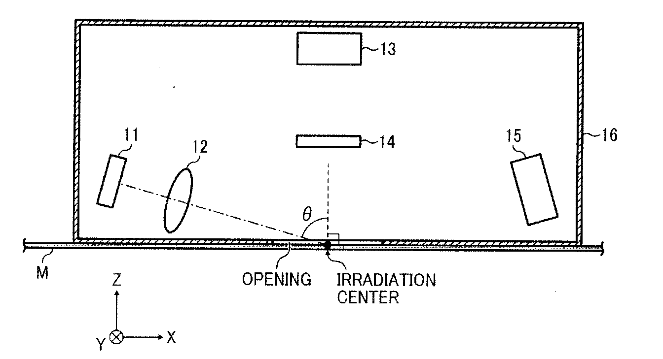
[0198]The color printer 2000 according to the present example embodiment uses the sensor apparatus 100 in place of the optical sensor 2245, arranged near the operation panel outside the printer cabinet 2200, and is used to determine the brand of the recording paper. In regard to the other aspects of the configuration, the color printer 2000 according to the present example embodiment is equivalent to that of the first example embodiment described above. For this reason, the description concentrates on the differences from the first example embodiment. In the description of the second example embodiment, like reference signs are given to elements similar to those described in the first example embodiment, and the descr...
third embodiment
[0346]Next, the third example embodiment of the present invention is described with reference to FIG. 50. The color printer 2000 according to the third example embodiment uses a sensor apparatus 300 in place of the sensor apparatus 100. In regard to the other aspects of the configuration, the color printer 2000 according to the third example embodiment is equivalent to that of the second example embodiment described above. For this reason, the description concentrates on the differences from the second example. In the description of the third example embodiment, like reference signs are given to elements similar to those described in the second example embodiment, and the description of such similar elements are omitted.
[0347]As illustrated in FIG. 50 as an example, the sensor apparatus 300 includes the light source 11, the collimate lens 12, the photosensors 13, 13t, and 15, the polarizing filter 14, the displacement sensor 54, the pressing member 61, the dark box 16, and the proce...
PUM
 Abstract
Description
Claims
Application Information
 - R&D
- Intellectual Property
- Life Sciences
- Materials
- Tech Scout
- Unparalleled Data Quality
- Higher Quality Content
- 60% Fewer Hallucinations
Browse by: Latest US Patents, China's latest patents, Technical Efficacy Thesaurus, Application Domain, Technology Topic, Popular Technical Reports.
© 2025 PatSnap. All rights reserved.Legal|Privacy policy|Modern Slavery Act Transparency Statement|Sitemap|About US| Contact US: help@patsnap.com


