
Sensors for measuring at least one of pressure and temperature, and related assemblies and methods

a technology of sensors and pressure and temperature, applied in the direction of fluid pressure measurement, measurement devices, instruments, etc., can solve the problems of quartz resonator sensors that are included in pressure transducers that are relatively expensive to fabricate, size, shape, configuration,

Inactive Publication Date: 2015-03-05
QUARTZDYNE
View PDF11 Cites 10 Cited by
  • Summary
  • Abstract
  • Description
  • Claims
  • Application Information

AI Technical Summary

Benefits of technology

The present patent describes a new generation of pressure sensors that use quartz resonators. These sensors have a compact design and can measure pressure with high accuracy. Several models are available, including a thickness shear mode resonator pressure sensor and a quartz resonator pressure sensor. The new sensors have a smaller size and can operate at higher frequencies, making them more versatile than older sensors. The technical effects of this patent include improved precision, accuracy, and efficiency in measuring pressure.

Problems solved by technology

Electrodes on the resonator element coupled to a high frequency power source drive the resonator and result in shear deformation of the crystal resonator.
However, each of the quartz resonator sensors that are included in a pressure transducer may be relatively expensive to fabricate, as each quartz resonator sensor must be individually manufactured.
The overall size and positioning requirements of each of such quartz resonator sensor in a pressure transducer may limit the size, shape, and configuration of the assembly, which is usually of significant concern given size constraints imposed by inner diameters of drill string and production string tubular components in which the sensor assembly may be disposed.
Furthermore, the size of each of such quartz resonator sensors and the resonating portion thereof will affect the speed and accuracy with which the sensor adjusts to changes in pressure and / or temperature and how quickly the sensor can reach thermal equilibrium.

Method used


Image

  • Sensors for measuring at least one of pressure and temperature, and related assemblies and methods
  • Sensors for measuring at least one of pressure and temperature, and related assemblies and methods
  • Sensors for measuring at least one of pressure and temperature, and related assemblies and methods

Examples


Embodiment Construction

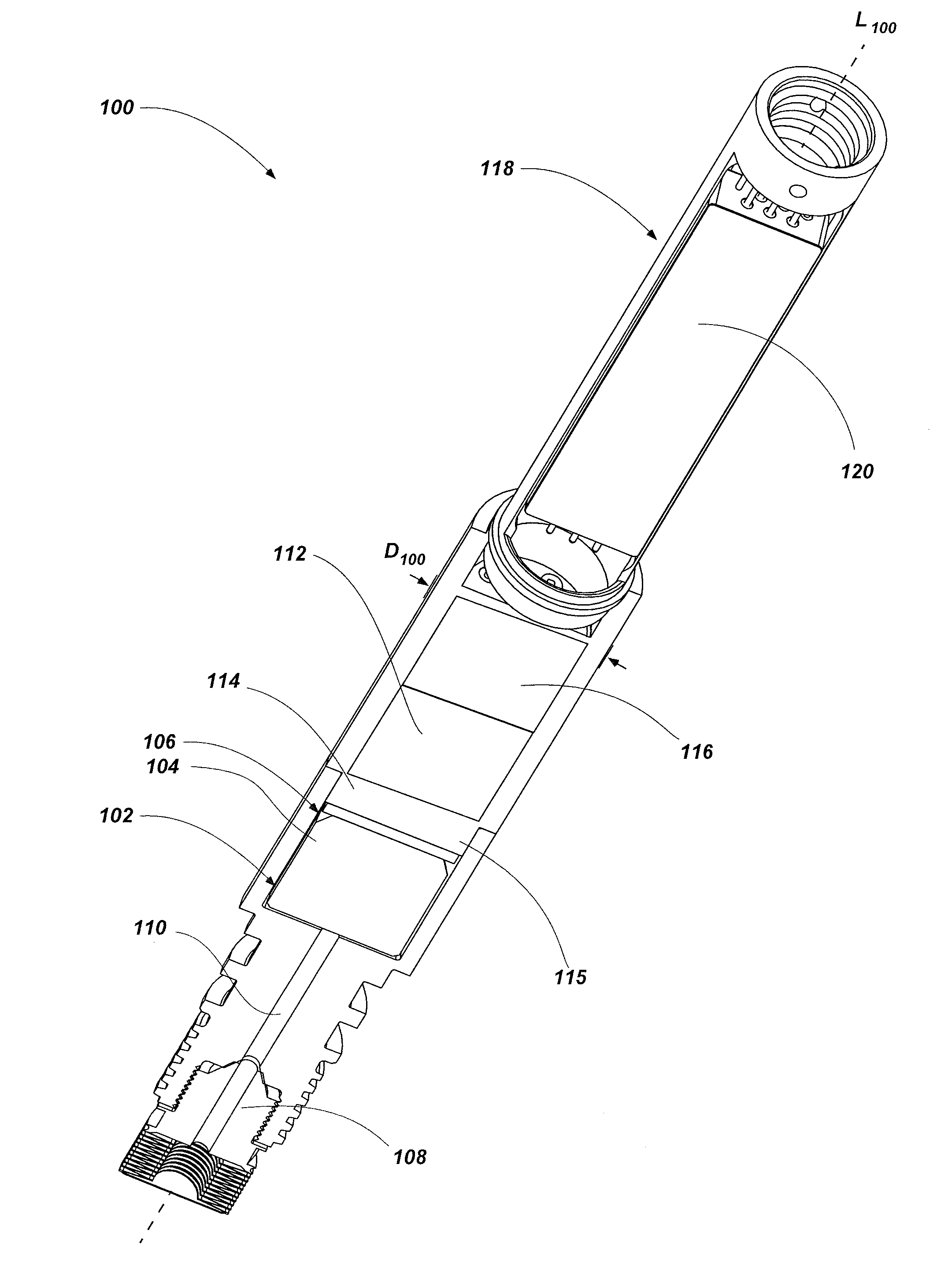
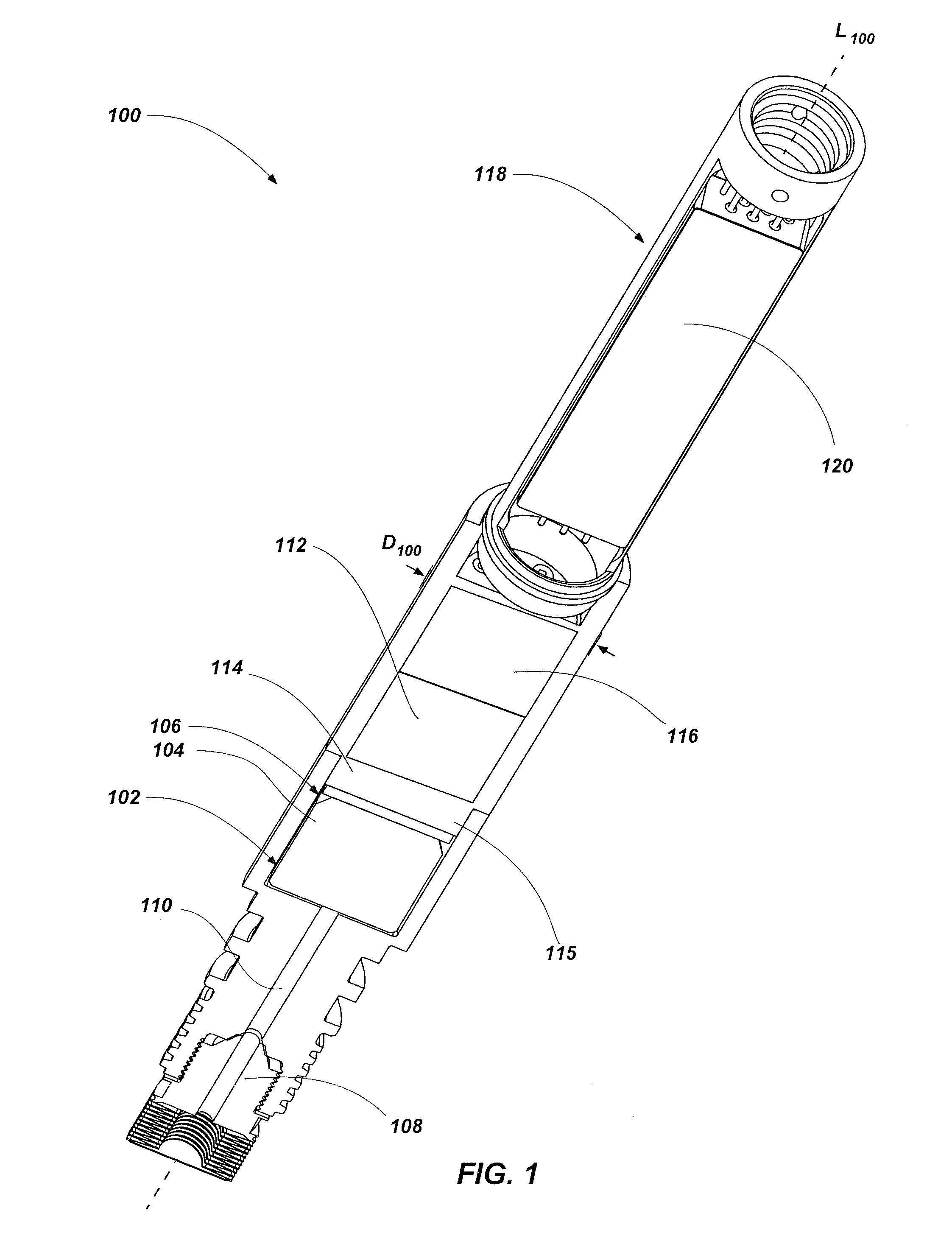
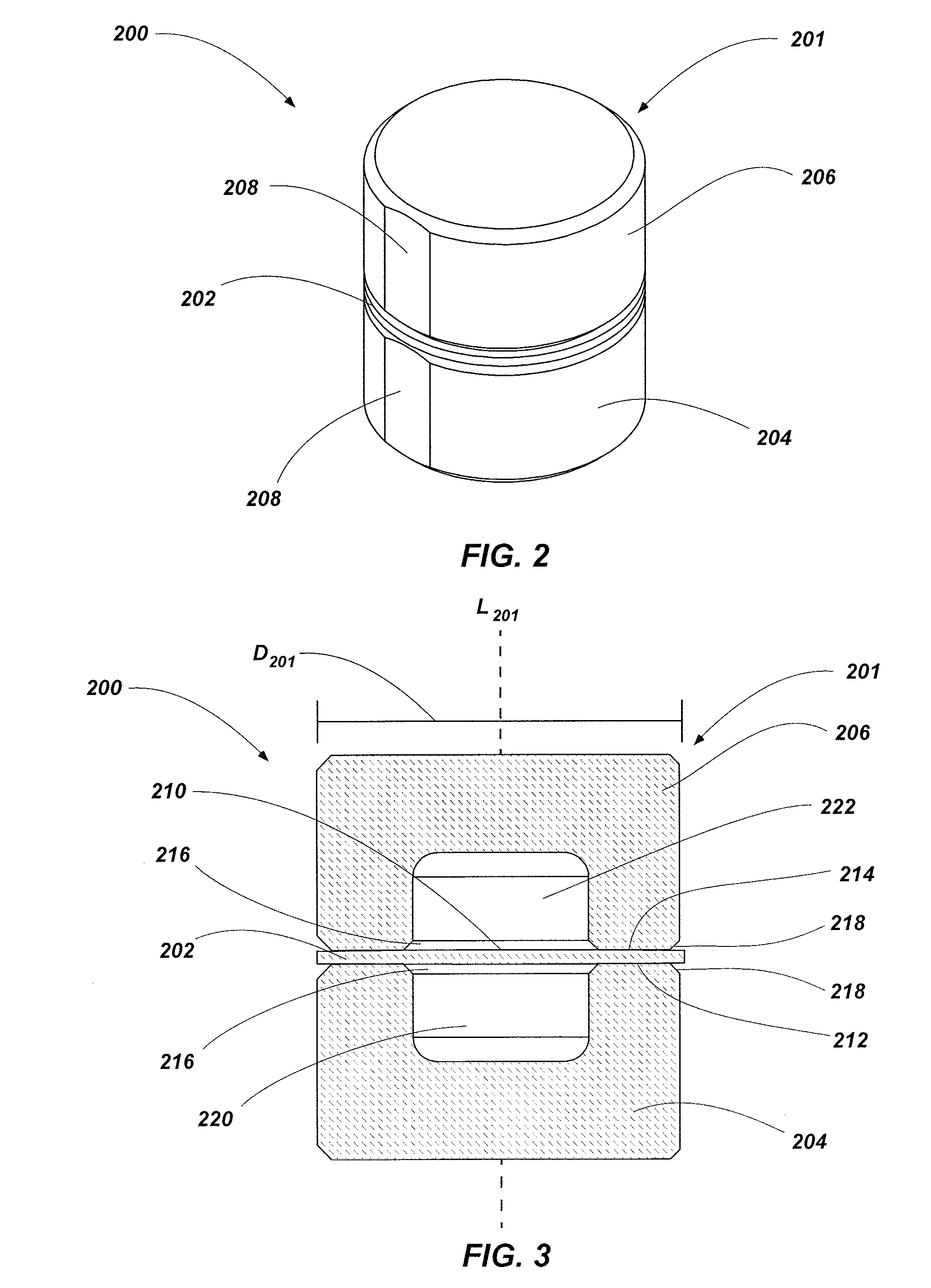
[0020]In the following detailed description, reference is made to the accompanying drawings that depict, by way of illustration, specific embodiments in which the disclosure may be practiced. However, other embodiments may be utilized, and structural, logical, and configurational changes may be made without departing from the scope of the disclosure. The illustrations presented herein are not meant to be actual views of any particular sensor, transducer, or component thereof, but are merely idealized representations that are employed to describe embodiments of the present disclosure. The drawings presented herein are not necessarily drawn to scale. Additionally, elements common between drawings may retain the same numerical designation.

[0021]Although some embodiments of sensors of the present disclosure are depicted as being used and employed in pressure transducer assemblies, persons of ordinary skill in the art will understand that the embodiments of the present disclosure may be ...


PUM

PropertyMeasurementUnit
thicknessaaaaaaaaaa
thicknessaaaaaaaaaa
thicknessaaaaaaaaaa

Abstract

Thickness shear mode resonator pressure sensors include a housing having an outer dimension that is less than 0.575 inch (14.605 millimeters). Pressure transducers may include a quartz pressure sensor and a quartz reference sensor, wherein an electronics assembly of the pressure transducer is configured to drive at least one of the quartz pressure sensor and the quartz reference sensor at a frequency greater than 10 MHz. Transducer assemblies include an electronics assembly configured to drive at least one quartz sensor of the transducer assembly at a frequency greater than 10 MHz.

Description

CROSS REFERENCE TO RELATED APPLICATION[0001]This application claims the benefit of U.S. Provisional Patent Application Ser. No. 61 / 873,149, filed Sep. 3, 2013 entitled “SENSORS FOR MEASURING AT LEAST ONE OF PRESSURE AND TEMPERATURE, AND RELATED ASSEMBLIES AND METHODS,” the disclosure of which is incorporated herein by reference in its entirety.TECHNICAL FIELD[0002]Embodiments of the present disclosure relate to sensors for measurement of at least one of a pressure and temperature and, more particularly, to quartz resonator sensors for measurement of at least one of a pressure and temperature and related assemblies and associated methods.BACKGROUND[0003]Thickness shear mode quartz resonator sensors have been used successfully in the downhole environment of oil and gas wells for several decades and are an accurate means of determining downhole pressures in widespread use in hydrocarbon (e.g., oil and gas) exploration and production, as well as in other downhole applications. Quartz re...

Claims


Application Information

Patent Timeline
Patent Type & Authority Applications(United States)
IPC IPC(8): G01L9/00G01L19/00
CPCG01L19/0092G01L9/0022G01L19/0038
Inventor PUCCIO, DEREK W.ROSE, SHANE D.
Owner QUARTZDYNE
Learn More