Fuel tank mounting structure of saddle-ride-type vehicle

a technology of fuel tank and mounting structure, which is applied in the direction of anti-theft devices, cycle equipments, anti-theft cycle devices, etc., can solve the problems such as the difficulty of fastening the fastening member such as the bolt, and achieve the elimination of the mounting position facilitating the arrangement of the buffer member, and preventing the effect of adverse influence on the appearance of the vehicl

Active Publication Date: 2015-03-05
HONDA MOTOR CO LTD
View PDF6 Cites 3 Cited by
  • Summary
  • Abstract
  • Description
  • Claims
  • Application Information

AI Technical Summary

Benefits of technology

The present invention provides a fuel tank mounting structure for a saddle-ride-type vehicle that allows for improved arrangement of the buffer member and facilitates the fastening operation of the connecting member to the main frame. The buffer member is mounted on the fuel tank and overlaps with the main frame as viewed in a top plan view, while the connecting member is mounted on the fuel tank and overlaps with the buffer member. The buffer member can be independently mounted from the flange, with no restriction on the tank shape or buffer member position. This eliminates the need for additional parts to cover the mounting hole and improves the appearance of the vehicle. The buffer member is located inside the flange and along the outer surface of the fuel tank, making it less visible and improving the vehicle's appearance. The connecting member is fastened to the main frame using a mount rubber, ensuring easy fastening and improved operability. The key cylinder is located above and behind the head pipe, and a recessed portion is formed for easy access to the keys for rider's convenience.

Problems solved by technology

In such fastening, the connecting member is supported on the upper surface of the main frame by way of the buffer member and hence, there is no possibility that the fuel tank is displaced downward at the time of fastening so that the fastening of the fastening member such as a bolt becomes difficult.

Method used


Image

  • Fuel tank mounting structure of saddle-ride-type vehicle
  • Fuel tank mounting structure of saddle-ride-type vehicle
  • Fuel tank mounting structure of saddle-ride-type vehicle

Examples


Embodiment Construction

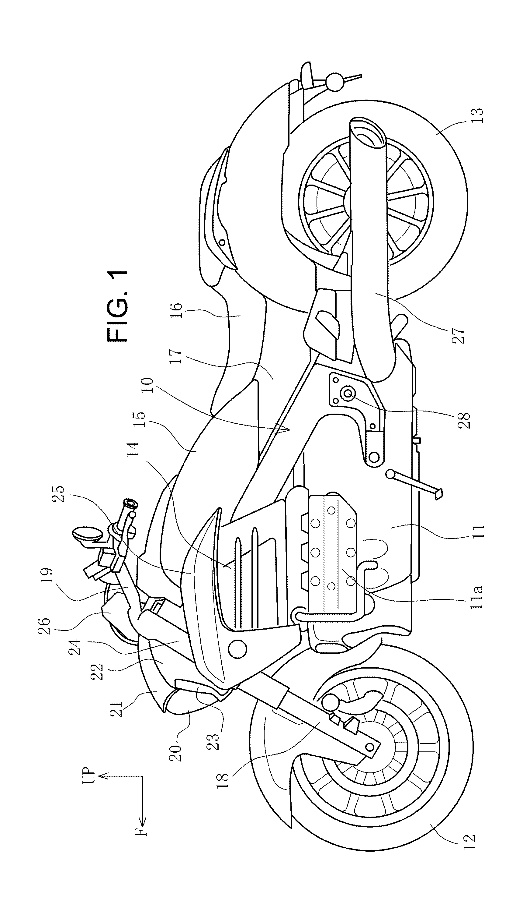
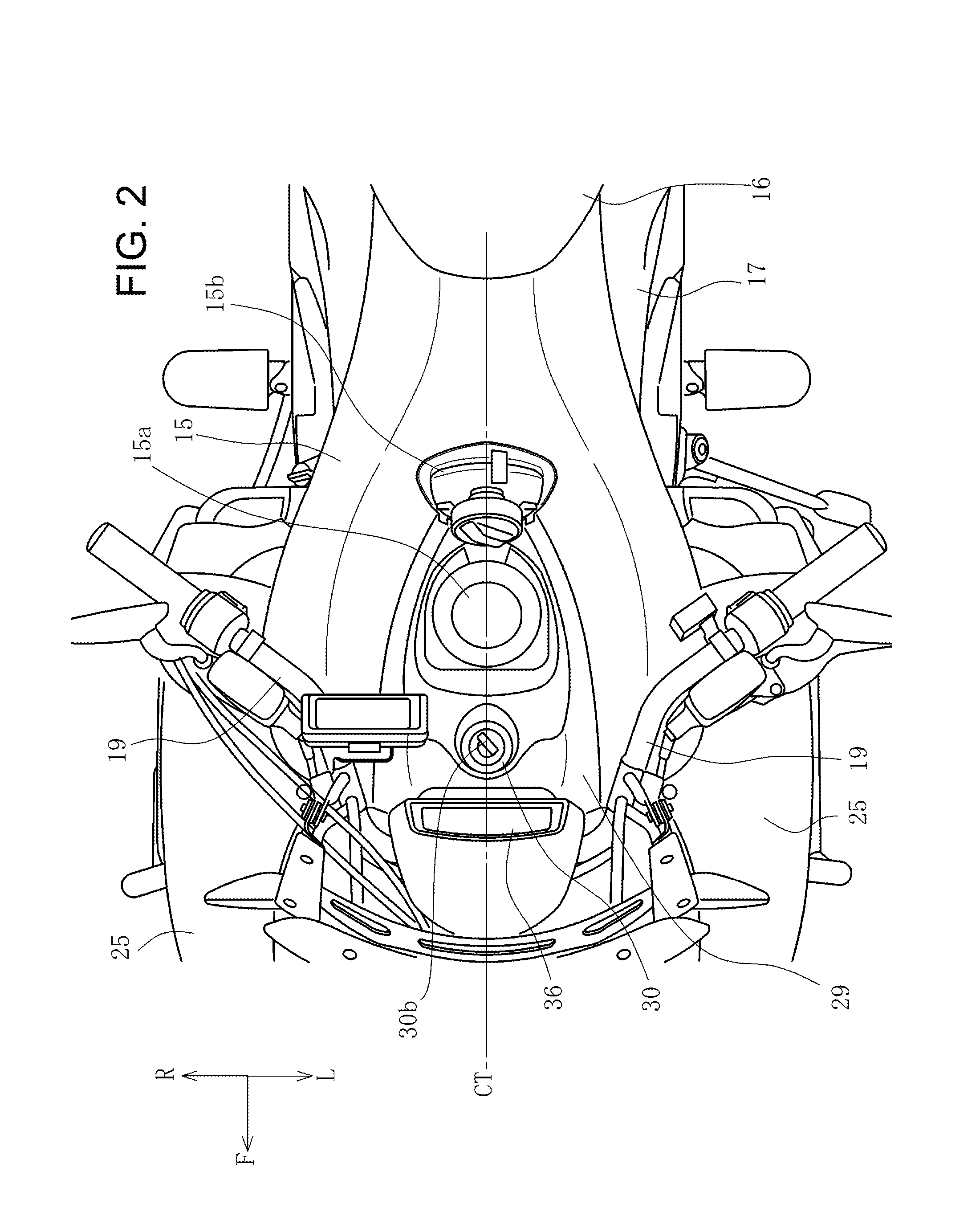
[0020]Hereinafter, one embodiment is explained by reference to drawings. Firstly, the overall constitution of a vehicle is schematically explained by reference to FIG. 1. In this specification, the directions such as frontward and rearward, upward and downward, and leftward and rightward are determined based on respective directions of the vehicle. In FIG. 1, a front side of the vehicle is indicated by an arrow F, and an upper side of the vehicle is indicated by an arrow UP. In FIG. 2, a left side of the vehicle is indicated by an arrow L, and a right side of the vehicle is indicated by an arrow R.

[0021]A motorcycle shown in FIG. 1 is a big motorcycle where a horizontally-opposed cylinder engine 11 is supported on a lower side of a vehicle body frame 10 at the center of a vehicle body, and a front wheel 12 and a rear wheel 13 are arranged in front of and behind the vehicle body frame 10 respectively. The engine 11 is a water-cooled engine, and radiators 14 are arranged above a cylin...


PUM


Abstract

A cushion rubber provided independent from a flange of a fuel tank. A fuel tank is arranged above a main frame. A tank front stay, which is mounted on a front lower portion of the fuel tank, is made to overlap with a tank-front-side mounting boss, which is formed on a front end bent portion of the main frame, and is fastened to the tank-front-side mounting boss using a bolt from sideward. The tank front stay is provided independently from a flange, is welded to a bottom surface of the fuel tank, and projects downward from the inside of the flange. A sleeve portion is mounted on a lower end of the tank front stay, and a mount rubber is inserted into the sleeve portion thus providing a rubber mount.

Description

BACKGROUND OF THE INVENTION[0001]1. Field of the Invention[0002]The present invention relates to a fuel tank mounting structure of a saddle-ride-type vehicle, and more particularly to a mounting structure arranged on a front side of a fuel tank.[0003]2. Description of Related Art[0004]There has been known a fuel tank mounting structure where a fuel tank is supported on a main frame which constitutes a vehicle body frame, a bracket is mounted on a front end portion of the fuel tank, the bracket is fixed to the vehicle body frame from above using bolts, a buffer member is mounted in a hole formed in a flange portion which is mounted on a lower portion of a side portion of the fuel tank in a downwardly extending manner, and an upper surface of the buffer member is brought into contact with a bottom surface of the fuel tank and a lower surface of the buffer member is brought into contact with an upper surface of the main frame (see JP-A-2013-124078).[0005]In the structure where the buff...

Claims


Application Information

Patent Timeline
Patent Type & Authority Applications(United States)
IPC IPC(8): B62J35/00B62H5/04
CPCB62H5/04B62J35/00Y10T70/5969
Inventor NISHIDA, YOICHIKAWAMURA, MITSUYA
Owner HONDA MOTOR CO LTD
Why Eureka
Try Eureka