
Sensor and method for continuous health monitoring

Active Publication Date: 2015-02-26
WAYNE STATE UNIV
View PDF4 Cites 98 Cited by
  • Summary
  • Abstract
  • Description
  • Claims
  • Application Information

AI Technical Summary

Benefits of technology

The patent is discussing the importance of making sensors that can be easily plugged into different devices without needing any extra parts. The ideal sensor should be small, low-cost, and provide a direct digital interface to a microcontroller. This approach has been highly successful with the accelerometer, which is now being used in various markets like smart phones, car safety, and home entertainment.

Problems solved by technology

Such form factors of the current technology are not well suited for 24-hour monitoring because it is expensive and / or uncomfortable to the patient.
The large size, however, causes patient discomfort or limits mobility.
While costs are moderate (more than about $100), it is still too expensive to be ubiquitously accepted by health care providers.
Current devices also consume too much power to provide 24 hour operation.

Method used


Image

  • Sensor and method for continuous health monitoring
  • Sensor and method for continuous health monitoring
  • Sensor and method for continuous health monitoring

Examples


Embodiment Construction

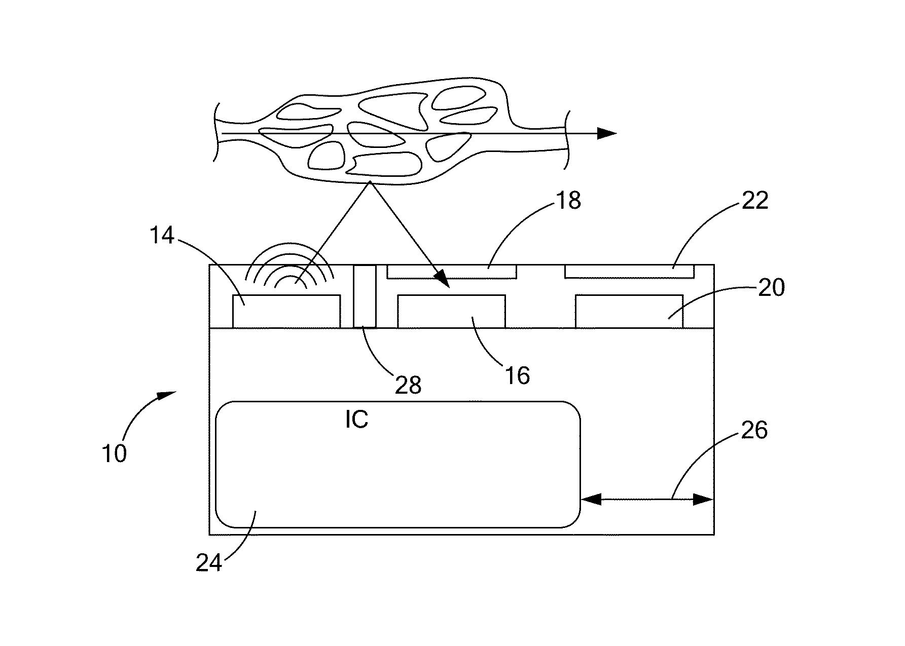
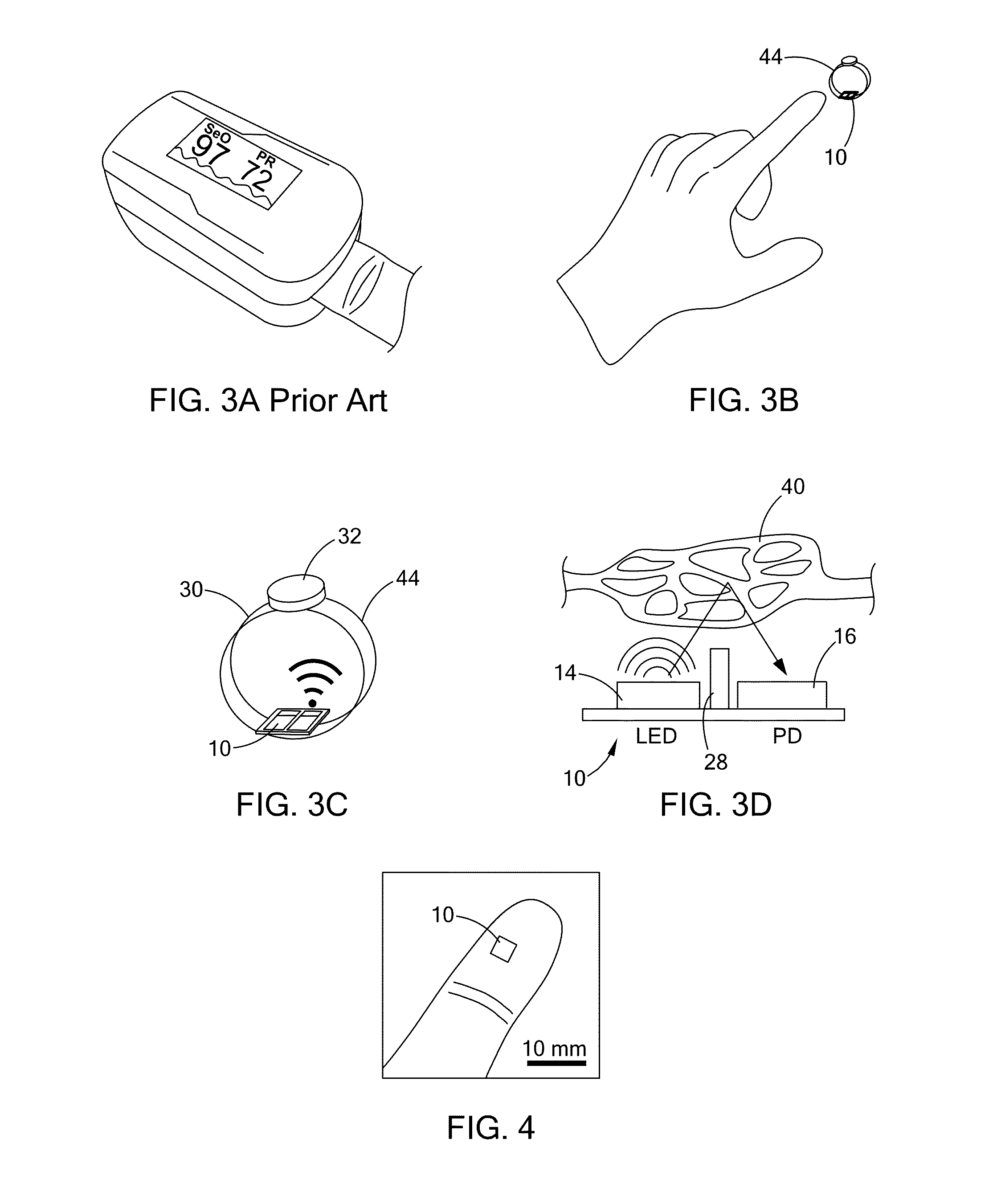
[0034]This invention includes new technologies for simultaneously sensing heart rate, blood pressure and pulse oximetry. These technologies can be combined in one sensor. The blood pressure may be indirectly measured using pulse wave velocity by placing several sensors in different locations along an artery. In this manner, vascular conditions can be detected, such as restricted blood flow.

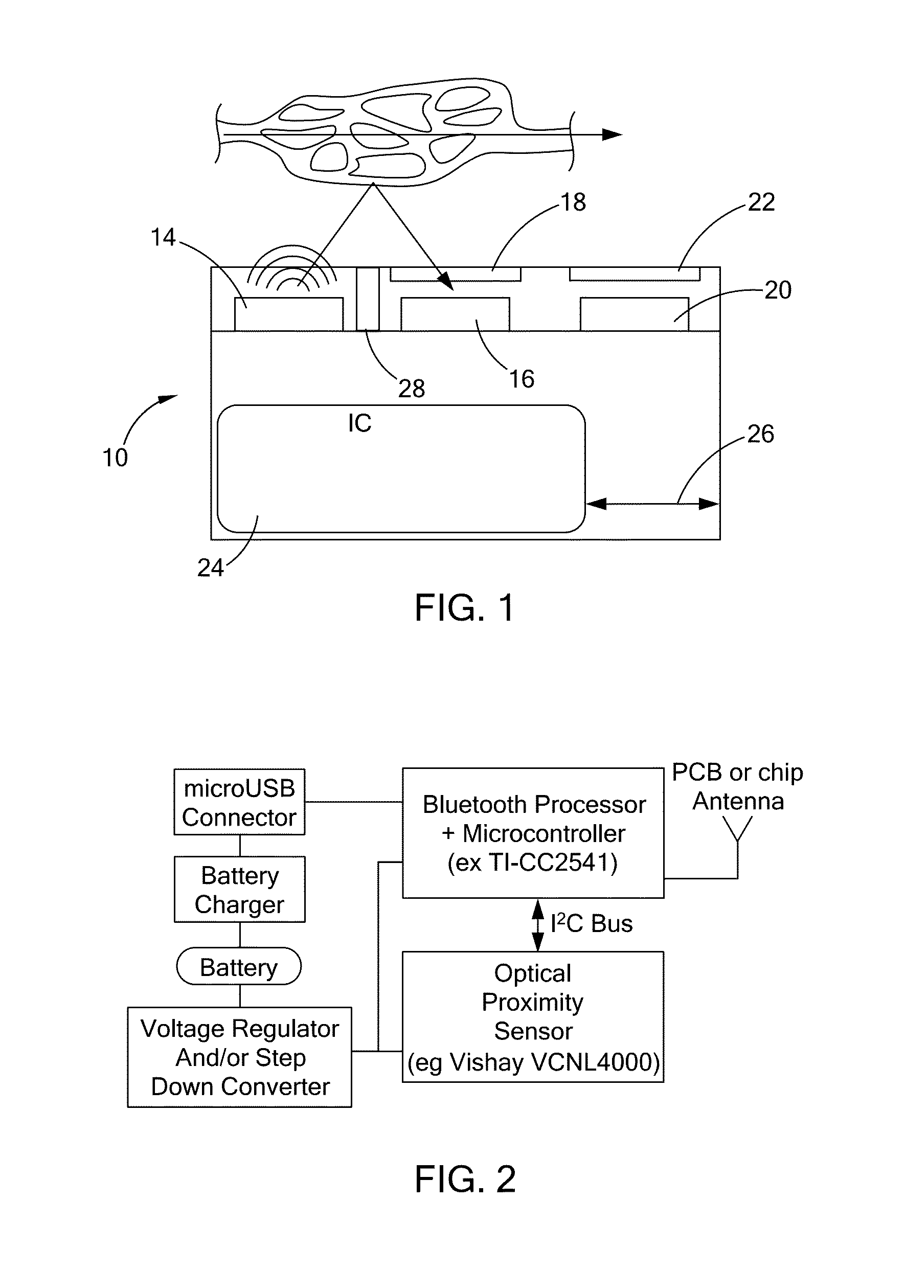
[0035]In a first approach, this device utilizes electronic optical proximity sensors (OPS) 10 to sense a patient's heart rate. Optical proximity sensors, also called light beam sensors, detect distance by measuring the magnitude of light reflected from an object. Variations of OPS are widely used for non-contact distance measurement in a variety of applications. In smart phones, for example, OPS detect when a phone is placed in a pocket, triggering touch-screen locking. In factory robotics, OPS are used for motion feedback control. In many industrial and consumer applications, OPS serve as touchle...


PUM


Abstract

An optical proximity sensor assembly includes an optical proximity sensor with an IR LED emitting light having an infrared wavelength, an IR photo detector sensitive to the infrared wavelength, an optical barrier blocking direct light rays from the LED to the IR photo detector and permitting reflected light rays to reach the at least one photo detector; and an electronic integrated circuit with an amplifier for amplifying a signal detected by the photo detector, an analog to digital converter, LED drivers, noise reduction and ambient light cancellation circuitry, and a digital interface for communication with a microcontroller. The optical proximity sensor is accommodated on a wearable carrier. A single sensor may include a plurality of identical or different LEDs, a plurality of photodiodes, or both. Also, several sensors may be placed on a person's skin along a vascular path to obtain data relating to blood flow and artery stiffness.

Description

CROSS-REFERENCE TO RELATED APPLICATIONS[0001]This application claims the priority of U.S. Provisional Application No. 61 / 626,524, filed on Mar. 28, 2012, and entitled “Sensor for Continuous Health Monitoring,” the entire disclosure of which is hereby included by reference.TECHNICAL FIELD[0002]The present invention relates to a device, a system, and a method for vascular health monitoring of a person. More particularly, the invention relates to a sensor suitable for remote patient monitoring.BACKGROUND OF THE INVENTION[0003]Remote patient monitoring (RPM), also called telehealth or telemonitoring, is a growing trend in modern health care with a multi-billion dollar market. This is useful for monitoring in many chronic diseases, including cardiovascular health, chronic fatigue syndrome, depression, and related ailments, and sleep-related ailments such as insomnia or sleep apnea.[0004]Remote patient monitoring has an important role in the management of patients at-risk for complication...

Claims


Application Information

Patent Timeline
IPC IPC(8): A61B5/024A61B5/02A61B5/0285A61B5/1455A61B5/00
CPCA61B5/02433A61B5/14552A61B5/02007A61B5/0285A61B5/6826A61B5/02125A61B2562/0233A61B2562/04A61B2562/046
Inventor BASU, AMAR SARBBASESH
Owner WAYNE STATE UNIV
Learn More