Image forming apparatus, method of forming image, and image forming system

Active Publication Date: 2015-02-19
KONICA MINOLTA INC
View PDF2 Cites 21 Cited by
  • Summary
  • Abstract
  • Description
  • Claims
  • Application Information

AI Technical Summary

Benefits of technology

The present invention relates to an image forming apparatus, method of forming image, and image forming system capable of discharging unusable sheets based on set order information of the unusable sheets, when a jam has occurred in a sheet. The technical effects of the invention include improved production efficiency and prevention of waste by automatically identifying and discharging unusable sheets, increased flexibility in sheet conveyance paths, and improved control over sheet discharge destinations.

Problems solved by technology

By the way, there are problems that, in an image forming apparatus, the number of sheets conveyed inside the machine is increased in accordance with improvement of performance and an increase in size, and once a jam of a sheet occurs, it takes much time to handle the jam, and it becomes difficult to discharge a large number of sheets depending on a portion where the jam has occurred and more time is required for recovery.
For example, conventional sheet conveyance control has a structure in which, when sheets subjected to image formation are sent out to a post-processing unit or to a sheet discharge unit, normal conveyance cannot be performed if the sheets are not sent out in an original discharge order.
Meanwhile, when an unusable sheet purge function is implemented, the function being to discharge unusable sheets remaining inside the machine to an outside of the machine using a conveyance path at the time of occurrence of a jam, discharge may not be performed in the original order in which the sheets are supposed to be discharged, depending on a print mode or a position where the jam has occurred.
Therefore, there is a problem that, under control of conventional sheet conveyance, a physically conveyable unusable sheet needs to be manually removed in a state where the device is stopped.
Further, there is a problem that sheet conveyance control specific to unusable sheet purge needs to be implemented separately from the conveyance of usable sheets.

Method used


Image

  • Image forming apparatus, method of forming image, and image forming system
  • Image forming apparatus, method of forming image, and image forming system
  • Image forming apparatus, method of forming image, and image forming system

Examples


Embodiment Construction

[0040]Hereinafter, an embodiment of the present invention will be described with reference to the drawings. However, the scope of the invention is not limited to the illustrated examples.

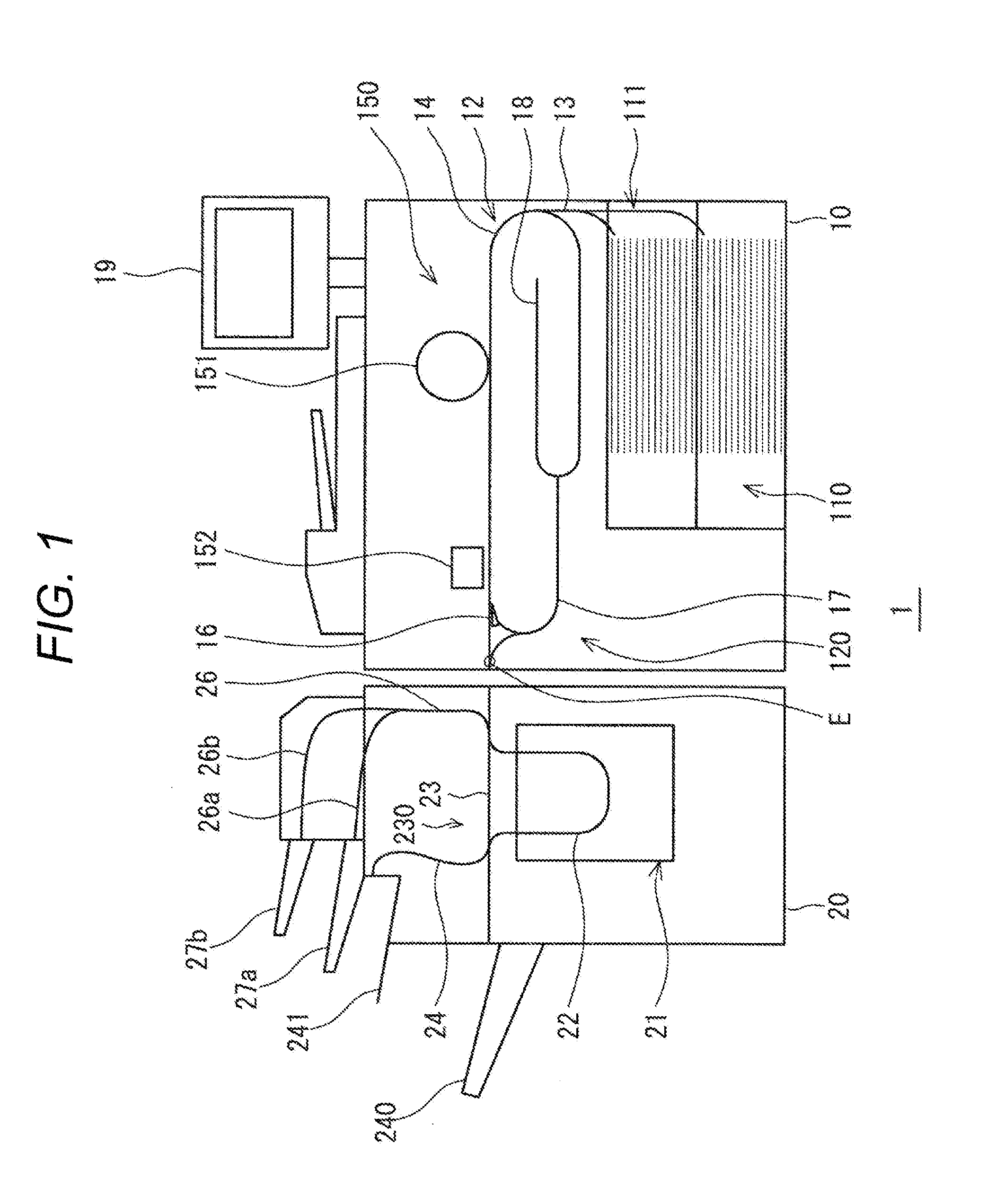
[0041]Hereinafter, an image forming apparatus and an image forming system according to an embodiment of the present invention will be described with reference to FIGS. 1 and 2.

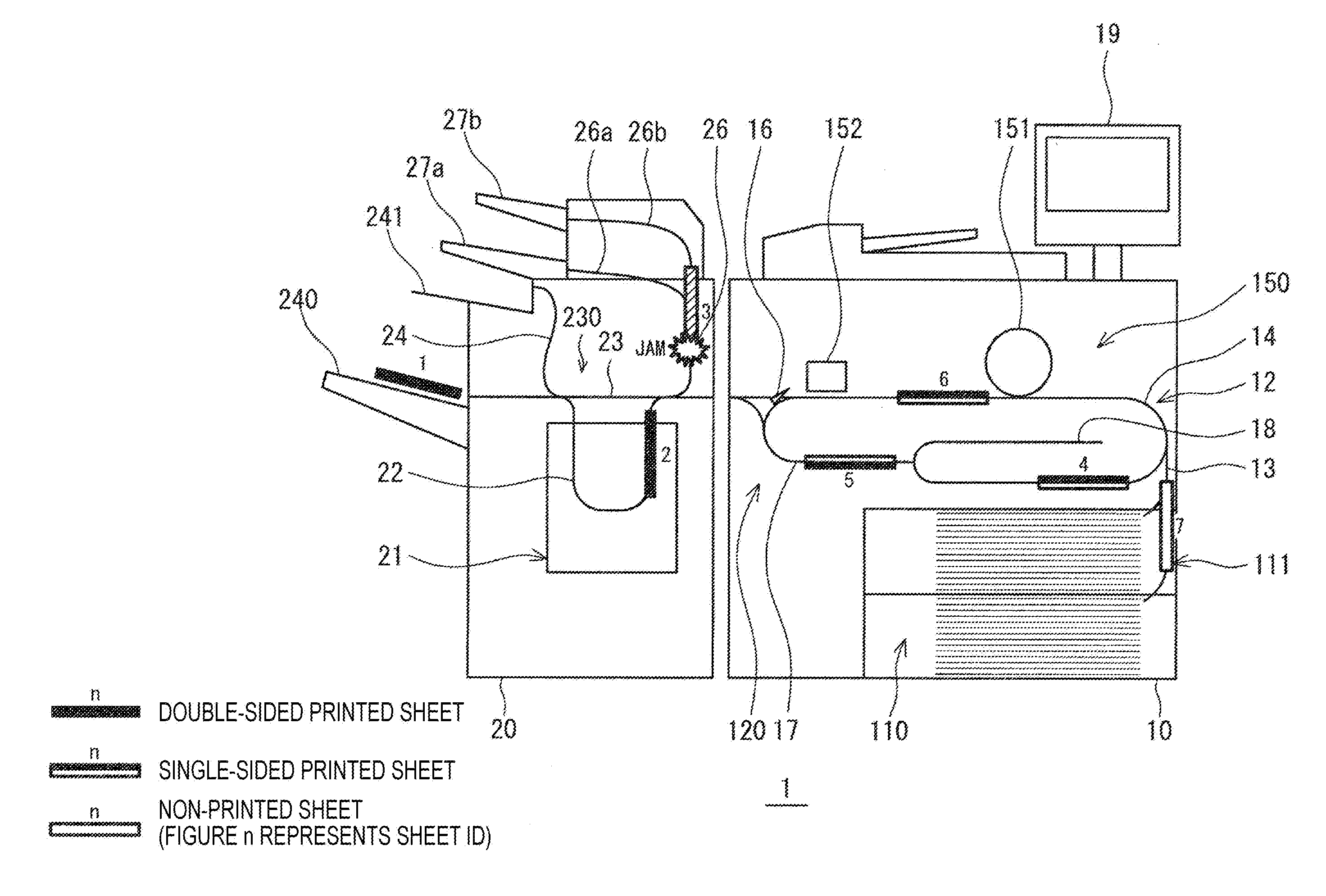
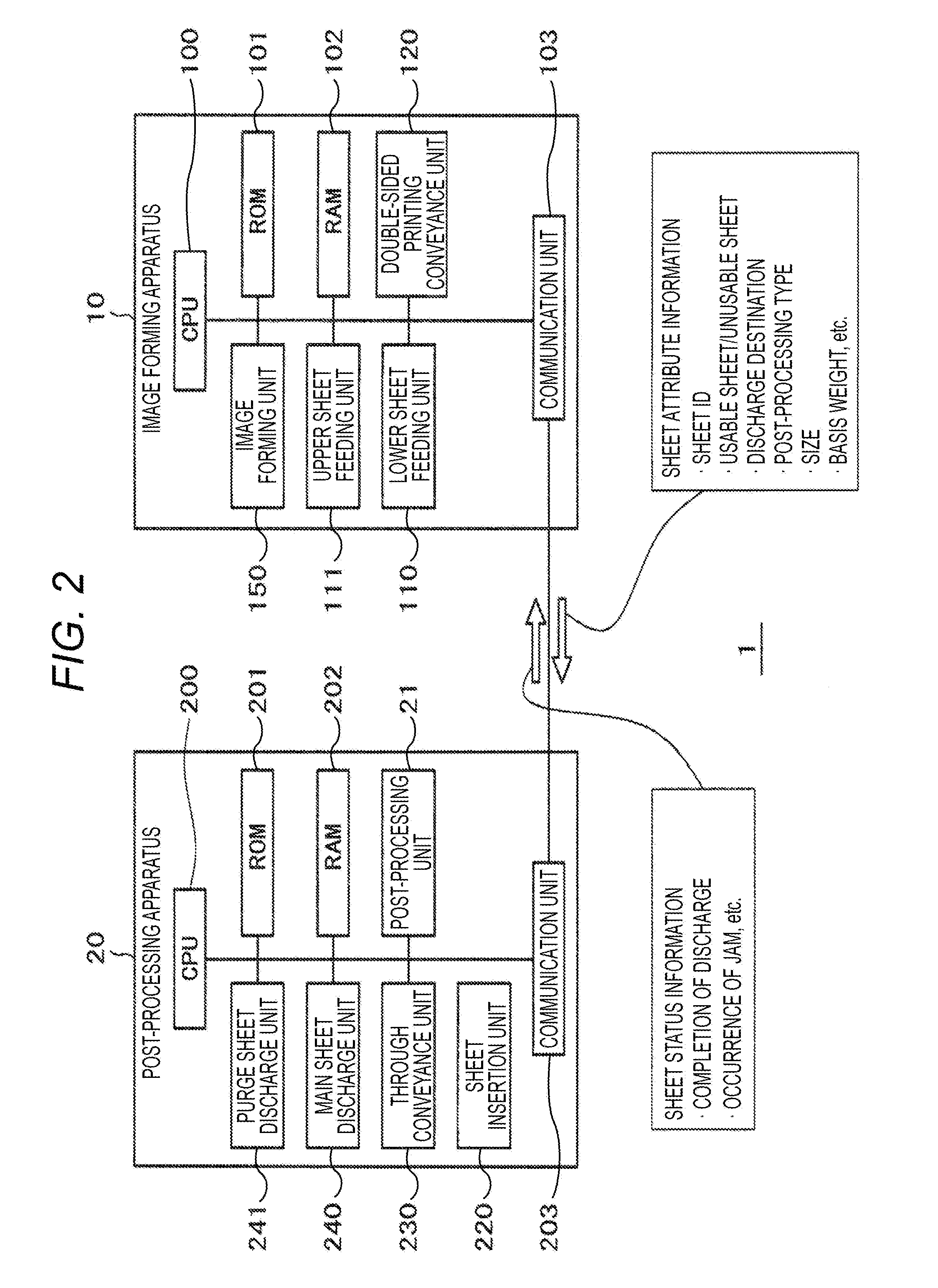
[0042]An image forming system 1 includes an image forming apparatus 10 and a post-processing apparatus 20. The post-processing apparatus 20 is one of external apparatuses of the present invention, and the number of the post-processing apparatuses 20 is not especially limited. Further, the present invention may be configured from only the image forming apparatus.

[0043]The image forming apparatus 10 includes a lower sheet feeding unit 110 and an upper sheet feeding unit 111 at a lower stage, and a sheet feeding path 13 is connected from the upper sheet feeding unit 111 to the lower sheet feeding unit 110. These units and the pat...


PUM


Abstract

An image forming apparatus includes: an image forming unit configured to form an image on a sheet based on a job; a sheet conveyance unit configured to convey a sheet through a conveyance path; and a control unit configured to control conveyance of a sheet, in which, when a jam has occurred in a sheet of during conveyance, the control unit sets order information of dischargeable sheets among unusable sheets remaining inside the apparatus after occurrence of the jam based on whether there is an unusable sheet on which image formation has been completed in the image forming unit, and discharges the unusable sheet to an outside of the apparatus through the conveyance path based on the set order information.

Description

[0001]The entire disclosure of Japanese Patent Application No. 2013-168052 filed on Aug. 13, 2013 including description, claims, drawings, and abstract are incorporated herein by reference in its entirety.BACKGROUND OF THE INVENTION[0002]1. Field of the Invention[0003]The present invention relates to an image forming apparatus, a method of forming an image, and an image forming system, which form an image on a sheet based on a job.[0004]2. Description of the Related Art[0005]A copying machine, a facsimile, a printer, or a multifunction machine provided with multi-functions thereof sequentially conveys sheets inside the machine, forms an image on a sheet, and discharges the sheet, and is based on the premise that the sheets are smoothly conveyed through a sheet feeding tray, or the like. A conveyance state of the sheets is grasped with various sensors. When a jam of a sheet is detected by the sensors, conveyance of the sheet is stopped, and sheets remaining inside the machine are dis...

Claims


Application Information

Patent Timeline
IPC IPC(8): G03G15/00G06K15/00B65H5/26H04N1/387B65H7/12B65H7/20
CPCG03G15/70B65H7/12G06K15/4085B65H5/26H04N1/3877B65H7/20B65H7/06B65H2511/528B65H2513/42H04N1/0032H04N1/00633H04N1/00641H04N2201/0091G03G15/5012G03G2215/00548B65H2220/01B65H2220/02
Inventor SAITSU, YASUSHI
Owner KONICA MINOLTA INC
Why Eureka
Try Eureka