
Buoyant target with laser reflectivity

a laser reflectivity and inflatable target technology, applied in the direction of reflecting targets, weapons, sport apparatus, etc., can solve the problems of not properly simulating the movement of a true battle target, unable to empty many conventional drogue chutes, and inability to provide a large number of “hard targets”

Inactive Publication Date: 2015-02-19
AMERICAN PACIFIC PLASTIC FABTORS
View PDF38 Cites 11 Cited by
  • Summary
  • Abstract
  • Description
  • Claims
  • Application Information

AI Technical Summary

Benefits of technology

The present invention is about a buoyant target with laser reflectivity. The target is made of a flexible material that can expand from a collapsed state to an inflated state. It includes one or more laser reflector members on its exterior surfaces that reflect laser light, such as infrared laser light. The target can also have a radar reflector device inside it that reflects a radar signal. The technical effects of this invention include improved visibility and detection of the target through the use of laser and radar signals.

Problems solved by technology

A problem associated with such targets is that they must often be large in size, which makes providing a large number of “hard targets” impractical.
Buoyant and inflatable targets, however, are susceptible water currents and waves, and more particularly to the wind, also known as set and drift, which cause the targets to move in a manner that does not properly simulate movements of a true battle target.
Many conventional drogue chutes cannot be emptied to permit convenient target recovery.
Proper sea anchors take time and experience to rig and launch, and the anchor line and commercial sea anchors cost money.
Many times a makeshift sea anchor is improperly rigged using a weighted ammunition shell casing or ammunition box full of scrap metal.
These types of sea anchors drop directly below the target balloon and exert too much resistance in heavy seas, resulting in damage to the target balloon before it can serve its intended purpose.
A problem with this approach is that the metal shavings can provide insufficient reflectivity, especially when the shavings settle to the bottom of the target over time.
A problem with this approach is that the metallic material, due to its electrical conductive properties, could present an electrical hazard during deployment and / or retrieval of the target on the deck of a ship.
Other approaches involving metal plates have the disadvantage of puncturing the inflatable target and making the target top heavy or unwieldy during deployment and retrieval of the target.

Method used


Image

  • Buoyant target with laser reflectivity
  • Buoyant target with laser reflectivity
  • Buoyant target with laser reflectivity

Examples


Embodiment Construction

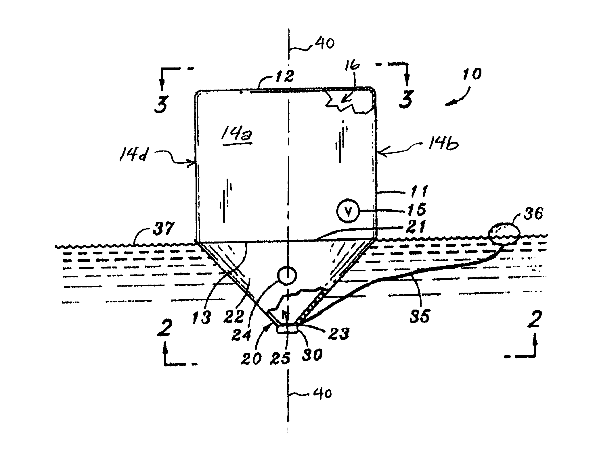
[0029]Referring now in more detail to the exemplary drawings for purposes of illustrating embodiments of the invention, wherein like reference numerals designate corresponding or like elements among the several views, there is shown in FIGS. 1-4 a buoyant target 10 made of a flexible membrane material so it can be collapsed and folded to a small bulk. Part of the buoyant target 10 can be inflated for deployment on water. The membrane material is impermeable to the inflating gas. Suitable materials include without limitation polyvinyl chloride and polyethylene sheeting, which are preferable because structural seams can be heat sealed, solvent sealed, or cemented as desired.

[0030]The buoyant target 10 has an inflatable structure 11 that comprises a top panel 12, a bottom panel 13 and a sidewall 14 which enclose an air-filled chamber 16 upon deployment. The inflatable structure is substantially airtight. The sidewall 14 is rectangular and has a front panel 14a, a right panel 14b, a rea...


PUM


Abstract

A buoyant target or ship decoy comprises an inflatable structure with a drogue chute attached to the periphery of the bottom of the inflatable structure. The drogue chute is an open flexible structure with a bottom end weighted with ballast to deploy it, and with ports through its side to permit water to flow into and out of it. A laser reflector member is attached to an exterior surface of the inflatable structure. The laser reflector member comprises a body having one or more laser reflective surfaces.

Description

CROSS-REFERENCE TO RELATED APPLICATION[0001]This application claims the benefit of U.S. Provisional Application No. 61 / 806,794, filed Mar. 29, 2013, which is incorporated herein by reference it its entirety.FIELD OF THE INVENTION[0002]This invention relates generally to a target for gunfire training and, more particularly, to a buoyant, inflatable target with laser reflectivity. The invention is optionally used for “man overboard” training exercises.BACKGROUND OF THE INVENTION[0003]Naval battle exercises involve shipborne weapons and floating targets to be hit by gunfire. It is often desired that the targets simulate the size and / or movement of boats and other floating objects. A problem associated with such targets is that they must often be large in size, which makes providing a large number of “hard targets” impractical. To address this, it is common practice to provide buoyant, inflatable and collapsible structures for targets. Such targets can be folded to a relatively small si...

Claims


Application Information

Patent Timeline
Patent Type & Authority Applications(United States)
IPC IPC(8): F41J2/00
CPCF41J2/00
Inventor HOCHSCHILD, III, ARTHUR ANTONHORECZKO, ROMANHOCHSCHILD, IV, ARTHUR ANTON
Owner AMERICAN PACIFIC PLASTIC FABTORS
Learn More