
Method of controlling physically separated network computers in one monitor and security system using the same.

a network computer and monitor technology, applied in the field of physical separation network computers in one monitor and a security system, can solve the problems of affecting the the cost of infrastructure construction is remarkably increased, and the security is relatively bad, so as to achieve the effect of rapid operation of the network switch

Inactive Publication Date: 2015-02-12
SMARTQ TECH
View PDF8 Cites 3 Cited by
  • Summary
  • Abstract
  • Description
  • Claims
  • Application Information

AI Technical Summary

Benefits of technology

This patent is about a better way to control multiple computers that are physically separate from each other. The goal is to prevent file copies between these computers, and to quickly connect the user's intended computer using only keyboard and mouse signals. This allows for faster and more efficient use of the network switch. Additionally, the patent allows for control of video information from multiple computers on one monitor using one keyboard and one mouse, which saves construction costs and resources.

Problems solved by technology

Also, it has developed various countermeasures on the exposure of sensitive data used in the internal network during using of the external network, the internal information leakage due to hackers, the access to the internal information due to the virus, and the material damages due to the Trojan malware, the worm malware, and the backdoor malware.
However, since a virtual space is utilized due to the share of the hard disk drive and a kernel process of the operating system is not completely controlled, there are defects in that it is very vulnerable to an external penetration, the security is relatively bad due to the easy invasion of the external accessor for malicious purposes, and the maintenance thereof is difficult in case of many computers.
However, there are problems in that the infrastructure construction cost is remarkably increased, the short problem of the power supply is generated in switch time between the internal and external networks, the switching between networks is time-consuming (at least 3-8 minutes), the operation efficiency thereof is deteriorated due to a discontinuous work, and it is a waste of resources such as two computers per person and two monitor per person.

Method used


Image

  • Method of controlling physically separated network computers in one monitor and security system using the same.
  • Method of controlling physically separated network computers in one monitor and security system using the same.
  • Method of controlling physically separated network computers in one monitor and security system using the same.

Examples


Embodiment Construction

[0019]Hereinafter, an exemplary embodiment of the present invention will be described in detail with reference to the accompanying drawings.

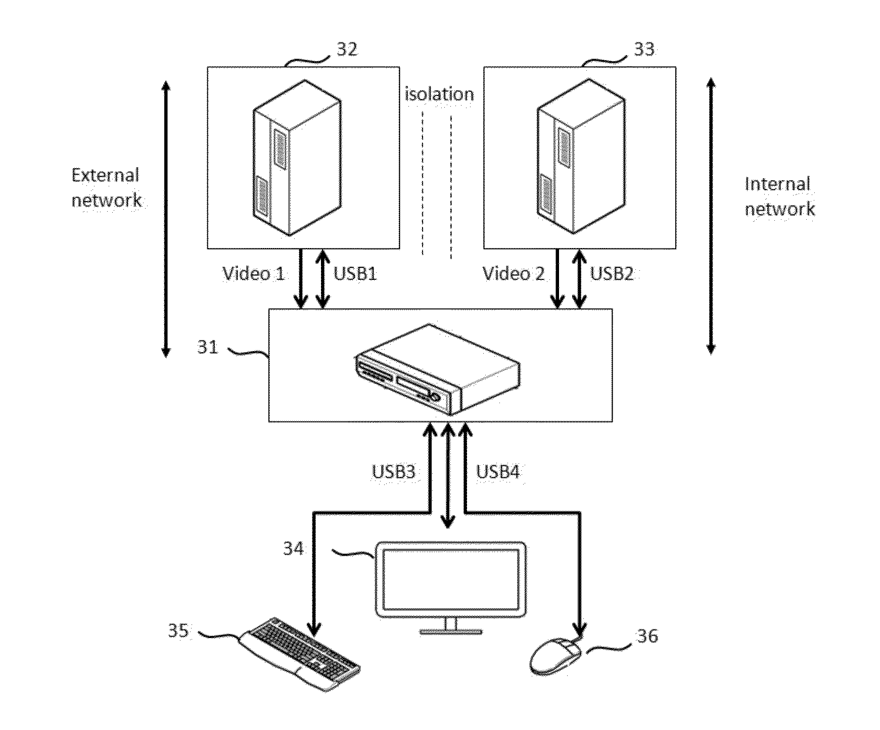
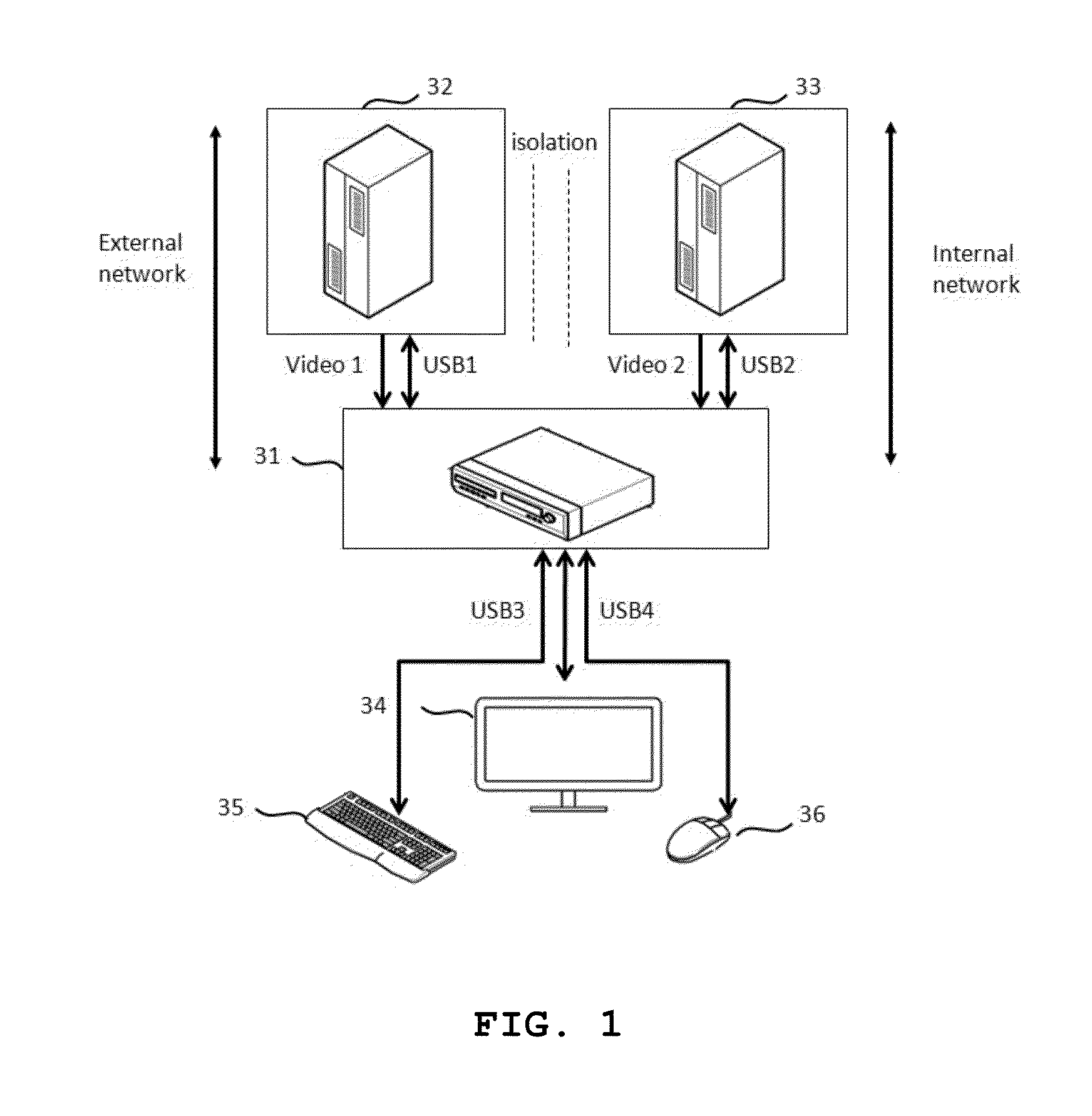
[0020]FIG. 1 is a schematic block diagram illustrating a security system of controlling physically separated network computers in one monitor according to the present invention.

[0021]As shown in FIG. 1, a security system of controlling physically separated network computers in one monitor includes a first computer 32, a second computer 33, a set-top box 31, a monitor 34, a keyboard 35, and a mouse 36.

[0022]The present invention has proposed a method of controlling a plurality of computers 32 and 33 through one monitor 34, one keyboard 35, and one mouse 36 connected to the set-top box 31 by means of a user without sharing data between the physically separated network computers.

[0023]Particularly, in the present invention, one communication channel for controlling the keyboard and the mouse is an input channel for inputting to the computers 32 and...


PUM


Abstract

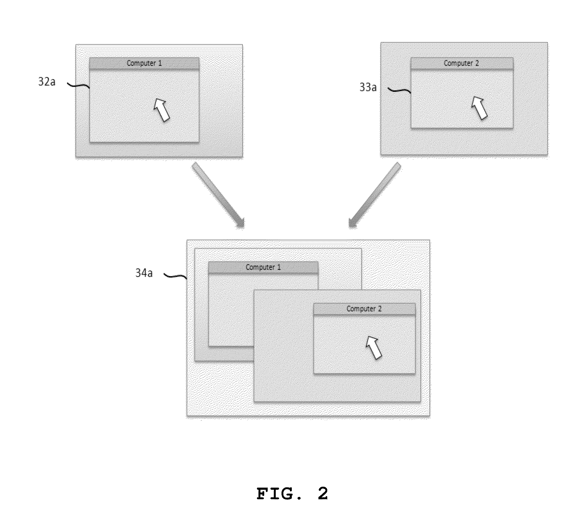
Disclosed is a method of controlling physically separated network computers in one monitor and a security system using the same in that a video information of two computers having physically separated networks is displayed on one monitor and controlled by means of a cursor, thereby reducing a video information throughput and implementing fast network switching.

Description

BACKGROUND OF THE INVENTION[0001]1. Field of the Invention[0002]The present invention relates to a method of controlling physically separated network computers in one monitor and a security system using the same. More particularly, the present invention relates to a method of controlling physically separated network computers in one monitor and a security system using the same in that a video information of two computers having physically separated networks is displayed on one monitor and controlled by means of a cursor, thereby reducing a video information throughput and implementing fast network switching.[0003]2. Description of the Prior Art[0004]Public institution or companies have blocked the illegal information leakage owing to an unauthorized access and have protected inside secrets and important files by means of a variety of security measures. Also, it has developed various countermeasures on the exposure of sensitive data used in the internal network during using of the ex...

Claims


Application Information

Patent Timeline
Patent Type & Authority Applications(United States)
IPC IPC(8): H04N21/41H04N21/431
CPCH04N21/4312H04N21/4113G06F3/1423G06F3/1454G09G5/006G09G5/026G09G2340/06G09G2360/18G06F21/70G06F21/82
Inventor LEE, GOWANGLOBAE, BYOUNGMIN
Owner SMARTQ TECH
Learn More