
Systems and methods for indoor navigation control by LED lighting devices

a technology of led lighting and indoor navigation, which is applied in the direction of navigation instruments, wireless communication, instruments, etc., can solve the problems of high power consumption, long time for a system to accurately position a device, and the blockage of gps satellite signals by high-rise buildings and rooms ceilings

Inactive Publication Date: 2015-02-05
ZHEJIANG SHENGHUI LIGHTING
View PDF2 Cites 27 Cited by
  • Summary
  • Abstract
  • Description
  • Claims
  • Application Information

AI Technical Summary

Benefits of technology

The patent describes a system that uses LED lighting devices, a location server, and a smart terminal to create a map of an unknown building. This system is able to more accurately position and navigate within indoor spaces, such as large shopping centers or museums.

Problems solved by technology

It often takes a long time for a system to accurately position a device when GPS technologies are used, which, as a result, requires high power consumption.
In addition, GPS satellite signals may be blocked by high-rise buildings and ceilings of rooms.
GPS technologies thus cannot be effectively used in an indoor environment or in an area having buildings with high density.
However, significant inaccuracies (e.g., in a range from a few hundreds to a few thousands meters) may occur.
Wi-Fi signal itself does not provide any positioning or navigation ability.
In addition, the Wi-Fi hotspot technologies are restricted by the service range.
Further, the Wi-Fi hotspot technologies cannot provide information regarding direction, speed, and / or other navigation data.
Furthermore, the Wi-Fi hotspot technologies cannot be used offline.

Method used


Image

  • Systems and methods for indoor navigation control by LED lighting devices
  • Systems and methods for indoor navigation control by LED lighting devices
  • Systems and methods for indoor navigation control by LED lighting devices

Examples


Embodiment Construction

[0030]Reference will now be made in detail to exemplary embodiments of the disclosure, which are illustrated in the accompanying drawings. Wherever possible, the same reference numbers will be used throughout the drawings to refer to the same or like parts.

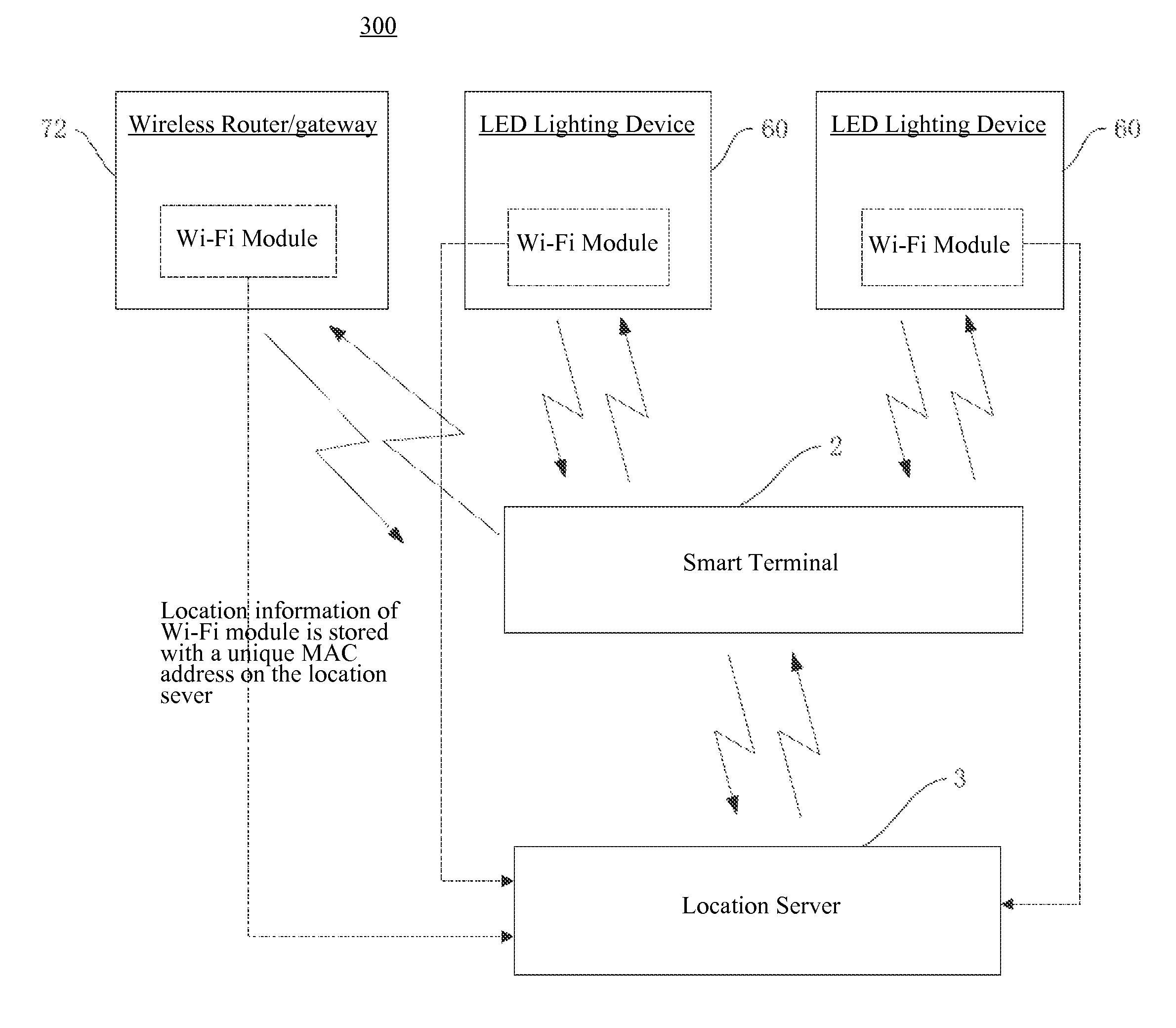
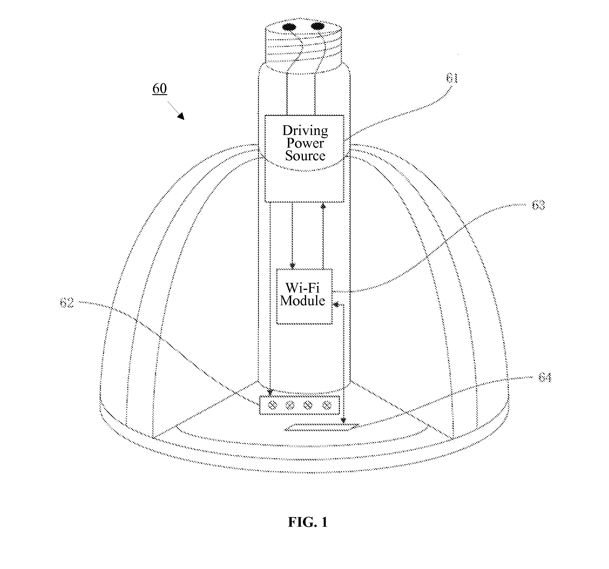
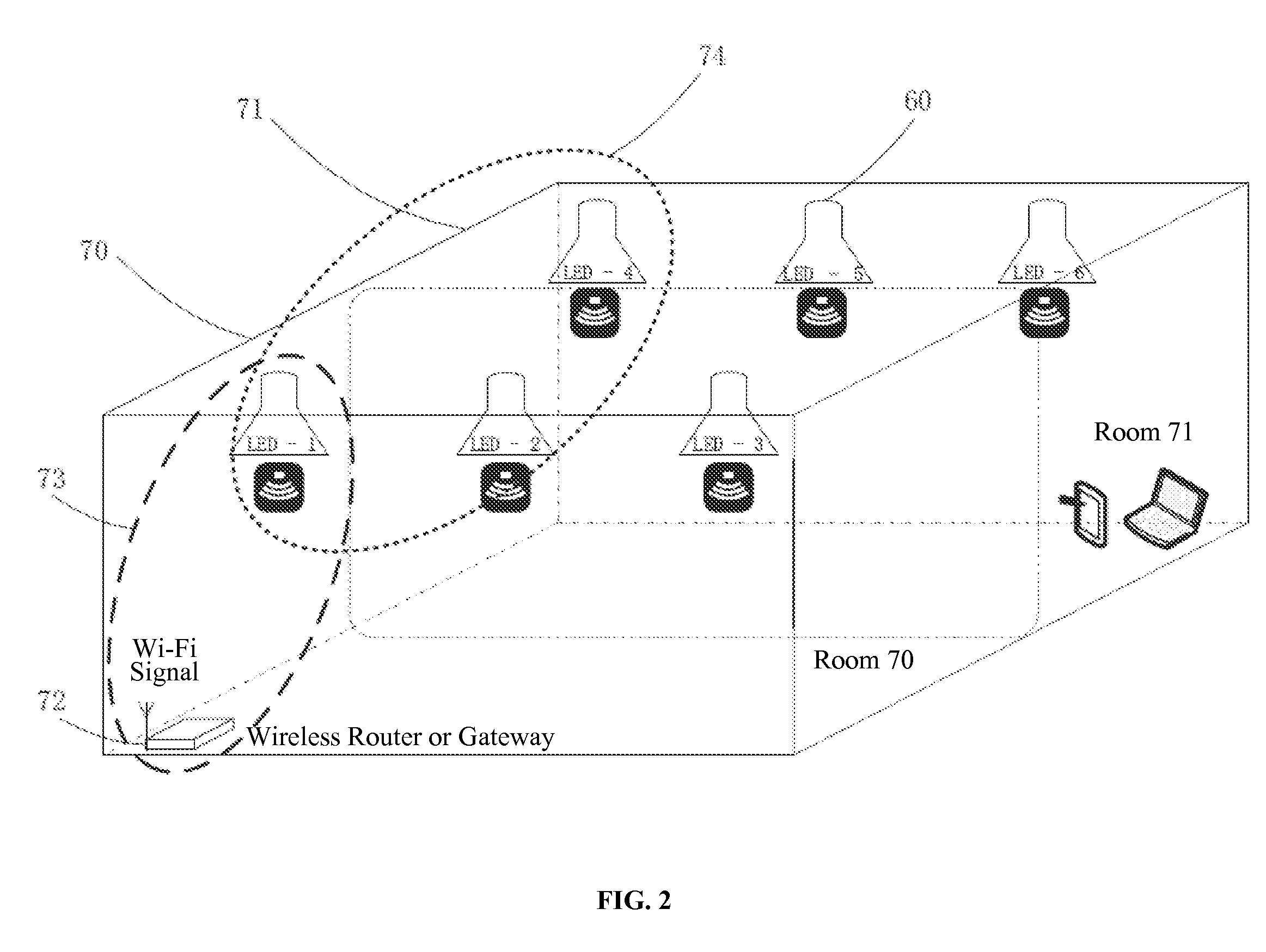
[0031]Systems and methods based on LED lighting devices for indoor navigation control are provided. Multiple LED lighting devices can be widely distributed and relatively fixed in an indoor environment. Each LED lighting device can contain a Wi-Fi module and can have its own location information stored in a location server and have its own unique MAC address. That is, the actual location of each LED lighting device can be bound with its own unique MAC address.

[0032]In one embodiment, when a user enters into an unknown building, by communications among LED lighting devices, the location server, and a smart terminal (e.g., a smart phone), a node distribution plan for the unknown building can be generated and mapped. Each node corres...


PUM


Abstract

Systems and methods for indoor navigation control by LED lighting devices are provided. The indoor navigation control system includes at least two LED lighting devices each including a Wi-Fi module as a wireless access node to receive a Wi-Fi signal and to transmit the received Wi-Fi signal to an adjacent node such that nodes within a Wi-Fi signal coverage area has an access to Internet or LAN. A location server is configured to store location information of the Wi-Fi module of each LED lighting device with a unique MAC address. The at least two LED lighting devices and the location server are configured to communicate with a smart terminal to calculate a position, a moving direction, and a moving speed of an object according to the location information of each LED lighting device along with a moving time length of the object for an indoor navigation.

Description

CROSS-REFERENCES TO RELATED APPLICATIONS[0001]This application is a continuation application of PCT Patent Application No. PCT / CN2014 / 082097, filed on Jul. 11, 2014, which claims priority to Chinese Patent Application No. 201310308124, filed on Jul. 18, 2013, the entire content of which is incorporated herein by reference.FIELD OF THE DISCLOSURE[0002]The present disclosure generally relates to the field of LED (i.e., light emitting diode) lighting technology and, more particularly, relates to systems and methods for indoor navigation control by LED lighting devices.BACKGROUND[0003]LED lighting may generally provide advantages in energy conservation, environmental protection, controllable lighting, solid state lighting, and long operational lifetime. LED lighting devices thus have been widely used in various areas for public, commercial, and indoor lighting.[0004]There has been an increasing focus on precise positioning and navigation to places of interest. Positioning technologies s...

Claims


Application Information

Patent Timeline
IPC IPC(8): G01C21/20H05B37/02H04W4/02H04W4/021H04W4/024H04W4/33
CPCG01C21/206H05B37/0272H04W4/023H04W4/021H05B47/19Y02B20/40H04W4/33H04W4/024
Inventor TUO, JIABINSHEN, JINXIANG
Owner ZHEJIANG SHENGHUI LIGHTING
Learn More