Filter Element for Liquid Filtration

Inactive Publication Date: 2015-02-05
MANN HUMMEL GMBH
View PDF3 Cites 0 Cited by
  • Summary
  • Abstract
  • Description
  • Claims
  • Application Information

AI Technical Summary

Benefits of technology

The invention proposes a filter element for liquid filtration with high resistance to aggressive liquids. The filter element has a simple structure consisting of two layers - a first layer made of cellulose and a second layer made of plastic fibers. The second layer prevents cellulose particles from the first layer from entering the liquid to be filtered. The plastic fibers in the second layer also have better chemical resistance and higher tensile strength than the cellulose particles, improving the overall mechanical strength of the filter element. The first and second layers can be connected to each other, and the overall composite of the two layers is strengthened by the connection. The filter element can also have embossings to improve its stiffness and reduce flow resistance.

Problems solved by technology

For example, when used over prolonged periods, oil can exhibit a decreasing pH value and thus can become chemically aggressive.

Method used


Image

  • Filter Element for Liquid Filtration
  • Filter Element for Liquid Filtration

Examples


Embodiment Construction

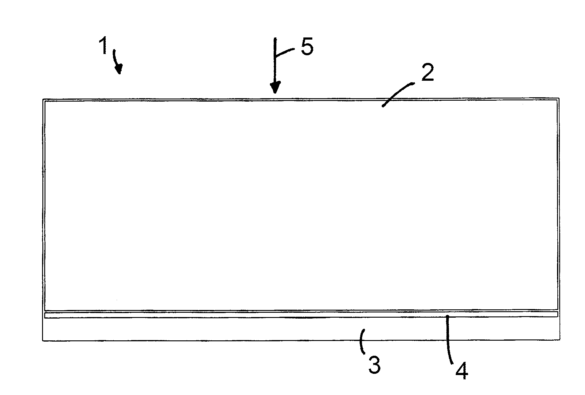
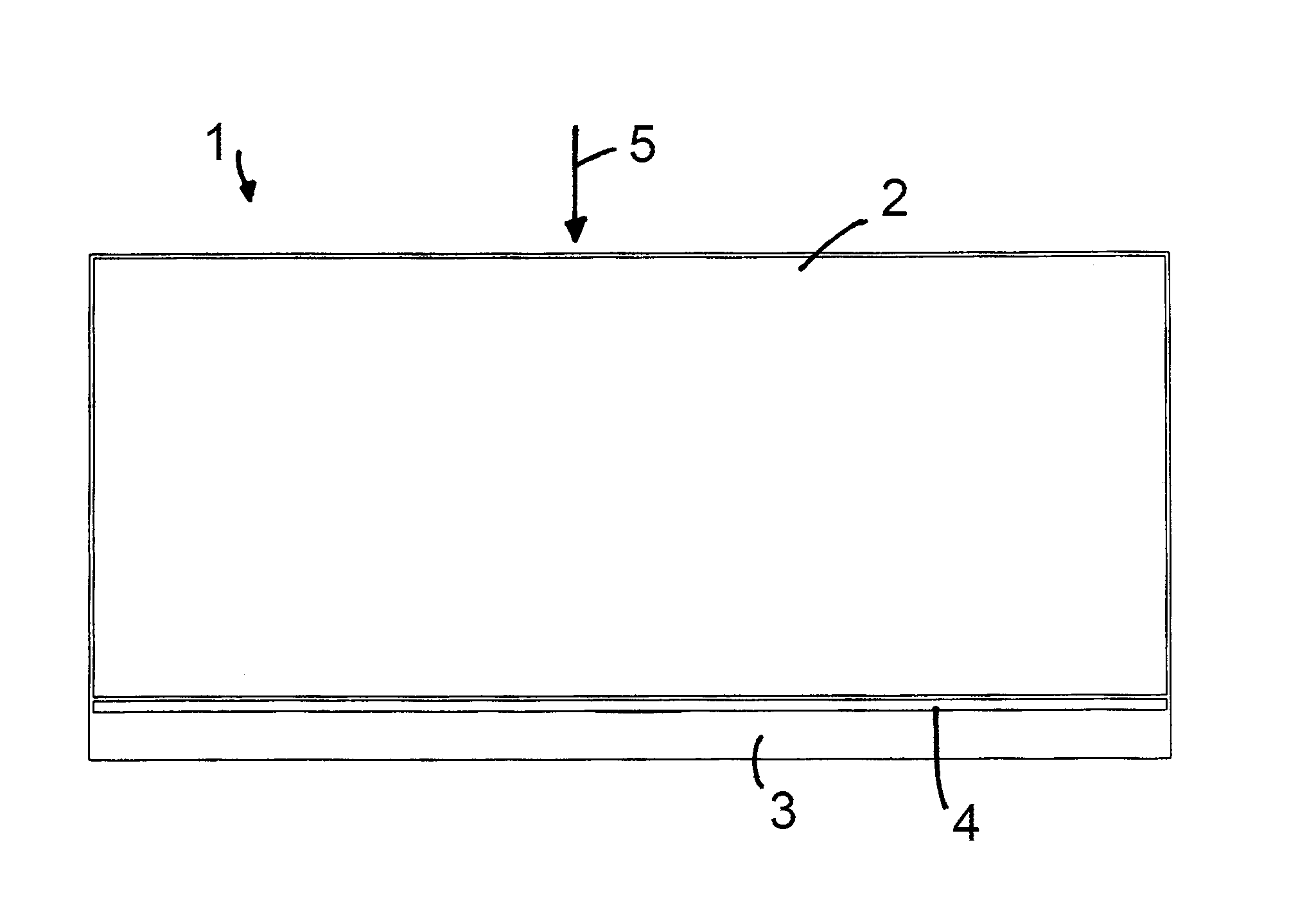
[0025]The filter element 1 illustrated in the FIGURE is used for filtering liquid, for example, in fuel filters or oil filters for motor vehicles. The plate-shaped filter element 1 is configured in two layers and has a first layer 2, primarily used for filtering the liquid, and an adjoining second layer 3, primarily having the function of stabilizing the first layer 2 and of retaining detached filter particles from the first layer 2 so as to prevent detached filter particles from being carried along in the cleaned liquid flow. The liquid to be cleaned flows in the direction of flow 5 through the filter element 1. The first filter layer 1 is located on the upstream side and the second layer 3 on the downstream side. The two layers 2 and 3 are connected to one another via an adhesive layer 4.

[0026]The first layer 2 has a thickness that is significantly greater than that of the second layer 3; the second layer 3 preferably has a thickness in the range between 0.1 mm and 0.2 mm, whereas...


PUM

PropertyMeasurementUnit
Thicknessaaaaaaaaaa
Thicknessaaaaaaaaaa
Thicknessaaaaaaaaaa

Abstract

A filter element for liquid filtration has a first layer and a second layer. The first and second layers are arranged one behind the other in the direction of flow. The first layer is a filter layer of cellulose, and the second downstream layer is a nonwoven of plastic fibers, wherein the second layer has a smaller thickness than the first layer.

Description

CROSS-REFERENCE TO RELATED APPLICATION[0001]This application claims the benefit of German patent application No. 10 2013 012 668.1, filed: Jul. 31, 2013, the entire contents of the aforesaid German patent application being incorporated herein by reference.BACKGROUND OF THE INVENTION[0002]The invention relates to a filter element for liquid filtration, wherein the filter element has two layers of different media which are arranged one behind the other in the direction of flow.[0003]Single-layer or multi-layer filter elements for liquid filtration which consist of cellulose or synthetic fibers are known. In the case of multi-layer filter elements, the different layers can differ either in terms of their constituents or their structure in one or more aspects. Thus, two-layer or multi-layer liquid filter elements are known in which the layers are constructed from different materials. Furthermore, single-layer liquid filter elements provided on one side with a micro-fiber layer, which, h...

Claims


Application Information

Patent Timeline
IPC IPC(8): B01D39/18B32B37/24B01D29/11B32B37/18B01D29/56B01D29/01
CPCB01D39/18B01D29/56B01D29/016B01D29/11B32B2307/726B32B37/24B32B2037/243B32B2305/026B32B37/182B32B37/12B32B38/08B32B2305/20B32B2309/105B01D39/1623B01D2239/0421B01D2239/0681Y10T156/10
Inventor EISENGRAEBER-PABST, JOBSTTRAUTMANN, PIUS
Owner MANN HUMMEL GMBH
Why Eureka
Try Eureka