Control device for internal combustion engine

a control device and internal combustion engine technology, applied in the direction of automatic ignition control, machines/engines, mechanical equipment, etc., to achieve the effect of increasing the control interval, and increasing the load of the operation region

Inactive Publication Date: 2015-02-05
TOYOTA JIDOSHA KK
View PDF32 Cites 16 Cited by
  • Summary
  • Abstract
  • Description
  • Claims
  • Application Information

AI Technical Summary

Benefits of technology

[0023]According to the first invention, in the forceful knock enabling region other than the low-speed pre-ignition region, a large in-cylinder pressure is regularly and forcefully generated, and the deposit accumulated in the cylinders can be removed. Therefore, consecutive occurrences of pre-ignition in the case in which the operation region enters the low-speed pre-ignition region thereafter can be restrained beforehand. Further, according to the first invention, the control interval is made longer as the load of the operation region is higher, and the control interval is made shorter as the load of the operation region is lower. Therefore, the deposit accumulated in the cylinders can be properly removed without giving stress more than required to the members configuring the internal combustion engine.
[0024]According to the second invention, an operation in the region with a load lower than in the forceful knock enabling region, namely the region in which deposit removal control cannot be executed continues for a predetermined time period or more, whereby the accumulated deposit can be removed in a short time period.
[0025]According to the third invention, the degree of the deposit removal control can be adjusted in accordance with the in-cylinder deposit accumulation amount.
[0026]An operation in the region with a load lower than in the forceful knock enabling region, namely, the region in which the deposit removal control cannot be executed continues for a predetermined time period or more, whereby a large amount of deposit is accumulated in the cylinder. According to the fourth invention, even when the operation region enters in the low-speed pre-ignition region in the state in which the deposit removal control is not sufficiently executed, an occurrence of pre-ignition can be restrained.

Problems solved by technology

Further, it is known that deposit that is accumulated in cylinders is one of the causes of generation of pre-ignition.

Method used


Image

  • Control device for internal combustion engine
  • Control device for internal combustion engine
  • Control device for internal combustion engine

Examples


embodiment 1

System Configuration of Embodiment 1

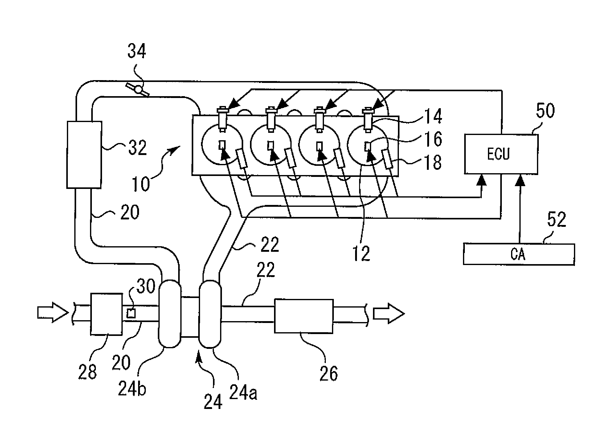
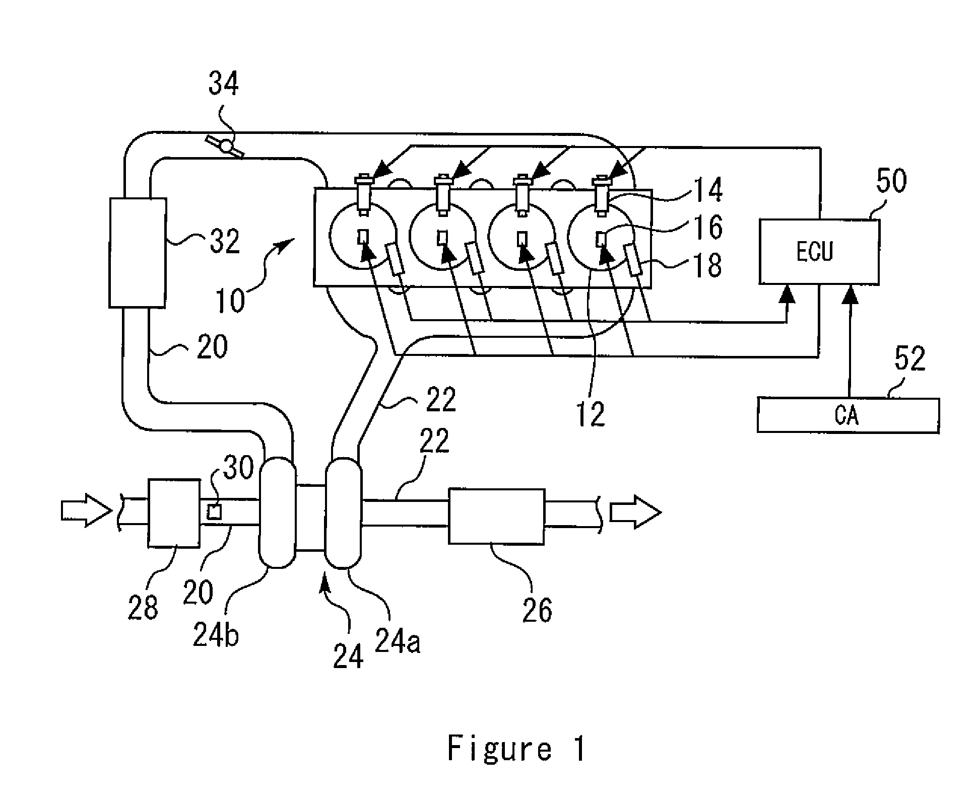
[0038]FIG. 1 is a conceptual view for explaining a system configuration of embodiment 1 of the present invention. The system shown in FIG. 1 includes an internal combustion engine (hereinafter also simply called an engine) 10. The internal combustion engine 10 is an engine that is downsized by supercharging. The internal combustion engine 10 includes a plurality of cylinders 12. The internal combustion engine 10 shown in FIG. 1 is of an inline-four engine type, but in the present invention, the number of cylinders and cylinder arrangement are not limited thereto.

[0039]Each of the cylinders 12 is provided with an injector 14 that directly injects fuel into the cylinder (a combustion chamber), an ignition plug 16 for igniting an air-fuel mixture, and an in-cylinder pressure sensor 18 that outputs a signal responsive to an in-cylinder pressure. To each of the cylinders 12, an intake passage 20 and an exhaust passage 22 are connected.

[0040]An exhaust ...

embodiment 2

System Configuration of Embodiment 2

[0063]Next, embodiment 2 of the present invention will be described with reference to FIG. 6. In a system of the present embodiment, the ECU 50 includes a second deposit removal control function that will be described later, in addition to the configuration of embodiment 1.

[Characteristic Function in Embodiment 2]

[0064]The deposit removal control of embodiment 1 is executed when the load of the operation region is higher than the lower limit load of the forceful knock enabling region. Meanwhile, the deposit removal control is not executed when the load of the operation region is lower than the lower limit load of the forceful knock enabling region. Therefore, if an operation in the lower load region than the forceful knock enabling region, namely, in the region where knocking does not occur continues for a long time period, a large amount of deposit is accumulated in the cylinders.

(Second Deposit Removal Control Function)

[0065]Therefore, the ECU 5...

embodiment 3

System Configuration of Embodiment 3

[0070]Next, embodiment 3 of the present invention will be described with reference to FIG. 7 to FIG. 10. In a system of the present embodiment, the ECU 50 includes a third deposit removal control function that will be described later, in addition to the configuration of embodiment 1 or 2.

[Characteristic Function in Embodiment 3]

[0071]FIG. 7 is a diagram showing a change of a thickness of a piston deposit film in a case of executing the deposit removal control described in embodiment 1. A broken line 68 represents a criteria at which pre-ignition due to deposit occurs. A solid line 74 expresses a change of a thickness of a piston deposit film at a time of using ordinary fuel, whereas a solid line 76 expresses a change of a thickness of a piston deposit film at a time of using inferior fuel. As shown by the solid line 76, at the time of using inferior fuel, a deposit accumulation amount increases as compared with at the time of using ordinary fuel, ...


PUM


Abstract

An object of the invention is to provide a control device for an internal combustion engine that regularly and forcefully removes deposit that is accumulated in cylinders and restrains consecutive occurrences of pre-ignition beforehand. The internal combustion engine has a low-speed pre-ignition region in which a possibility of occurrence of pre-ignition increases, in a low-rotation and high-load region. Ignition means (16) for igniting an air-fuel mixture taken into the cylinders is included. When an operation region is in a region other than the low-speed pre-ignition region and in a forceful knock enabling region with a load equivalent to or higher than a lower limit load at which knocking can be forcefully generated by advance of ignition timing, the ignition timing by the ignition means is forcefully advanced at a predetermined control interval, and a maximum in-cylinder pressure that is higher than at a time of ordinary combustion in the operation region and is lower than at a time of occurrence of pre-ignition is generated. The control interval is made longer as a load of the operation region is higher, and the control interval is made shorter as the load of the operation region is lower.

Description

TECHNICAL FIELD[0001]The present invention relates to a control device for an internal combustion engine, and more particularly relates to a control device for an internal combustion engine that is suitable for executing control of the internal combustion engine that is mounted on a vehicle.BACKGROUND ART[0002]Conventionally, it is known that abnormal combustion (hereinafter, called “pre-ignition”) occurs, in which an air-fuel mixture in a cylinder (a combustion chamber) self-ignites before ignition by an ignition plug, in an internal combustion engine that ignites and combusts a mixture of fuel and air by a spark of the ignition plug. Further, it is known that deposit that is accumulated in cylinders is one of the causes of generation of pre-ignition. When pre-ignition occurs, combustion which is more vigorous as compared with ordinary combustion (normal combustion) occurs.[0003]As a deposit removing art for the purpose of restraining an occurrence of pre-ignition, for example, the...

Claims


Application Information

Patent Timeline
Patent Type & Authority Applications(United States)
IPC IPC(8): F02B77/04F02P5/04F02P5/152
CPCF02B77/04F02P5/045F02P5/152F02D35/023F02P5/1502F02P5/1521F02P5/153Y02T10/40
Inventor YAGUCHI, HIROSHISHINODA, MASASHIKITAYAMA, TAKESHI
Owner TOYOTA JIDOSHA KK
Why Eureka
Try Eureka