Mobile communications network, infrastructure equipment and method

Active Publication Date: 2015-01-29
IPLA HLDG
View PDF10 Cites 0 Cited by
  • Summary
  • Abstract
  • Description
  • Claims
  • Application Information

AI Technical Summary

Benefits of technology

The present invention provides a mobile communications network that reduces congestion on the interface between base stations by establishing a separate communications bearer from the core network to each co-operating base station for communicating user data to the communications terminals. This reduces the burden on the interface between the base stations and allows for improved communication performance between the communications terminals and the network. The invention also allows the serving base station to stop transmitting the user data via the interface between the serving base station and the co-operating base station after the communications bearer between the serving base station and the co-operating base station has been established. These technical effects improve network performance and communication efficiency for mobile communications.

Problems solved by technology

However if there are many mobile stations which are transmitting or receiving data using the same co-operating set of base stations then because the interface between the serving base station and the co-operating base station (X2 interface) must carry scheduling assignments for transmitting the user data, control information as well as the user data to be communicated then the interface can become congested because of a limited bandwidth of the interface which is available.

Method used


Image

  • Mobile communications network, infrastructure equipment and method
  • Mobile communications network, infrastructure equipment and method
  • Mobile communications network, infrastructure equipment and method

Examples


Embodiment Construction

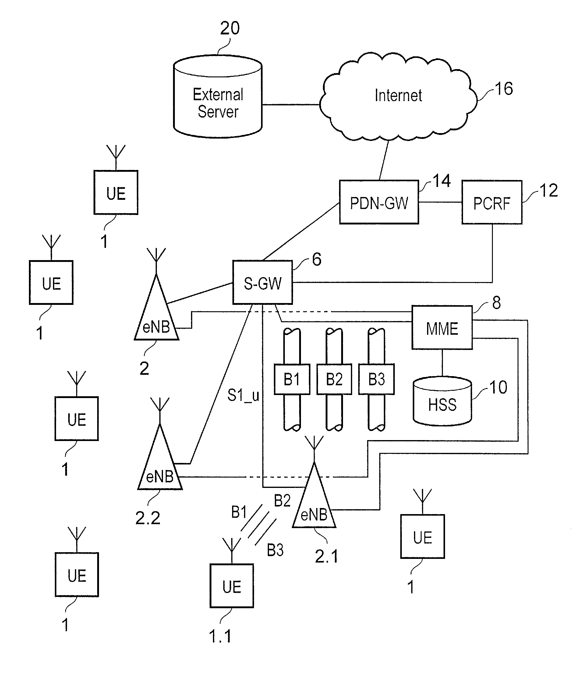
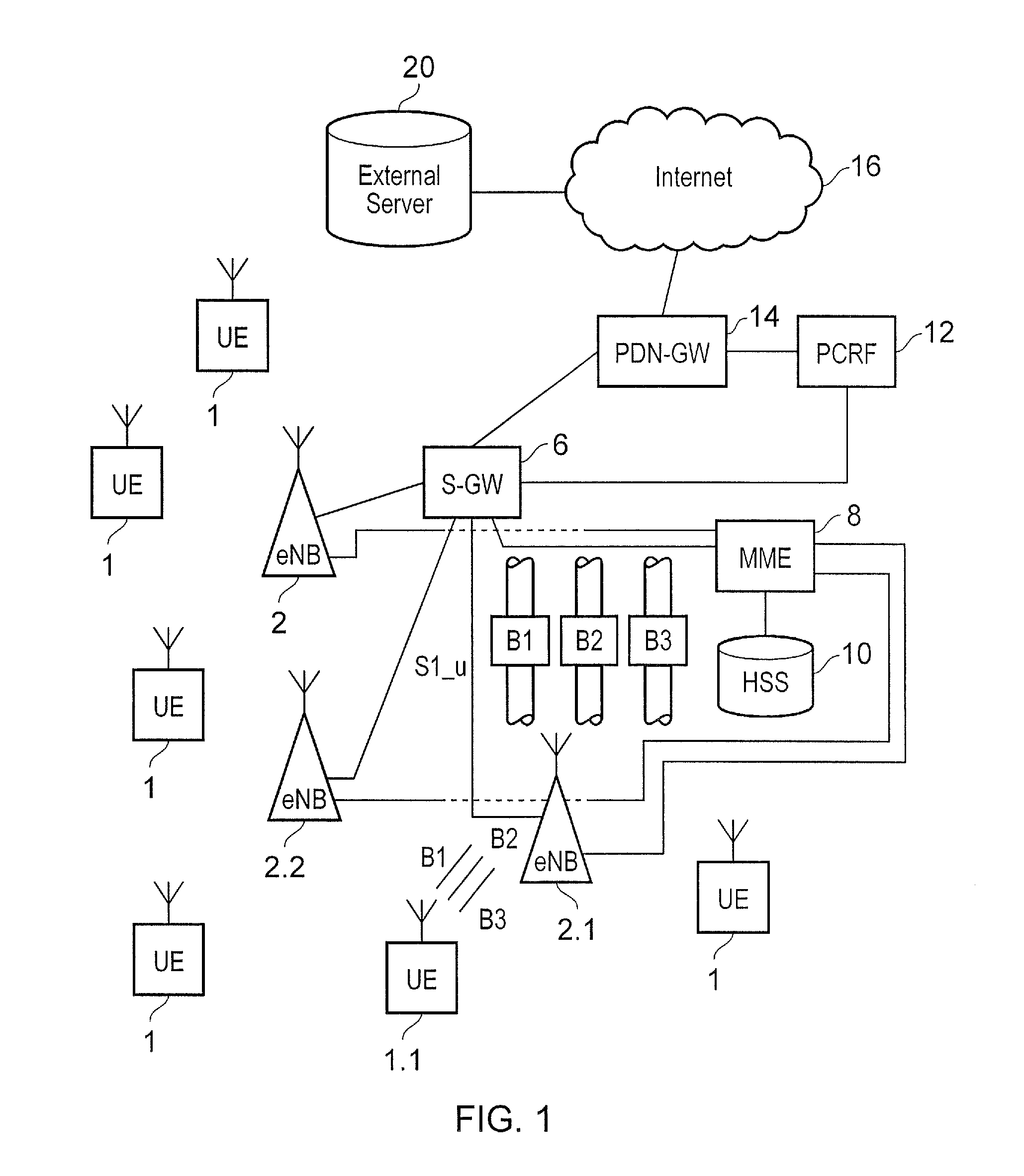
[0019]Embodiments of the present invention will now be described with reference to an implementation which uses a mobile communications network operating in accordance with the 3GPP Long Term Evolution (LTE) standard. FIG. 1 provides the example architecture of an LTE network. As shown in FIG. 1 and as with a conventional mobile communications network, communications terminals (UE) 1 are arranged to communicate data to and from base stations 2 which are referred to in LTE as enhanced NodeBs (eNB). For transmitting and receiving data via the wireless access interface the communications terminals 1 each include a transmitter / receiver unit 3.

[0020]The base stations or eNB's 2 are connected to a serving gateway S-GW 6 which is arranged to perform routing and management of mobile communications services to the communications terminals 1 as they roam throughout the mobile radio network. In order to maintain mobility management and connectivity, a mobility management entity (MME) 8 manages...


PUM


Abstract

A mobile communications network includes a core network including infrastructure equipment, and a radio network including plural base stations to provide a wireless access interface for communicating data to / from communications terminals. One base station operates as a serving base station to one of the communications terminals, to establish one or more communications bearers for communicating user data to / from the communications terminal via the core network and the radio network via the serving base station, and to co-operate with at least another base station to communicate the user data to / from the communications terminal. The mobile communications network can monitor a state of a radio communications channel between the co-operating base station and the communications terminal, and upon predetermined conditions, establish a communications bearer from the core network to the co-operating base station for communicating the user data to the co-operating base station transmitting the user data to the communications terminal.

Description

FIELD OF THE INVENTION[0001]The present invention relates to mobile communications networks for communicating data to and / or from communications terminals, infrastructure equipment, communications terminals and methods of communicating.BACKGROUND OF THE INVENTION[0002]Mobile communication systems have evolved over the past ten years or so from the GSM System (Global System for Mobiles) to the 3G system and now include packet data communications as well as circuit switched communications. The third generation project partnership (3GPP) has now began to develop a mobile communication system referred to as Long Term Evolution (LTE) in which a core network part has been evolved to form a more simplified architecture based on a merging of components of earlier mobile radio network architectures and a radio access interface which is based on Orthogonal Frequency Division Multiplexing (OFDM) on the downlink and Single Carrier Frequency Division Multiple Access (SC-FDMA) on the uplink.[0003...

Claims


Application Information

Patent Timeline
IPC IPC(8): H04W16/24H04W72/04
CPCH04W72/04H04W16/24H04W92/20H04W76/15H04W76/10H04W36/00695H04W24/00H04W28/16H04W36/18H04W36/28H04W72/23H04W72/542H04L5/0032H04W24/08H04W88/02
Inventor ZAKRZEWSKI, ROBERTTESANOVIC, MILOS
Owner IPLA HLDG
Why Eureka
Try Eureka