Radio communication system, radio base station, and mobile terminal

a radio communication system and mobile terminal technology, applied in the field of radio communication systems, radio base stations, mobile terminals, can solve the problems of reducing the efficiency of processing in the overall radio communication system, and achieve the effect of improving reception quality and enhancing interference suppression effects at mobile terminals

Inactive Publication Date: 2015-01-29
NTT DOCOMO INC
View PDF7 Cites 11 Cited by
  • Summary
  • Abstract
  • Description
  • Claims
  • Application Information

AI Technical Summary

Benefits of technology

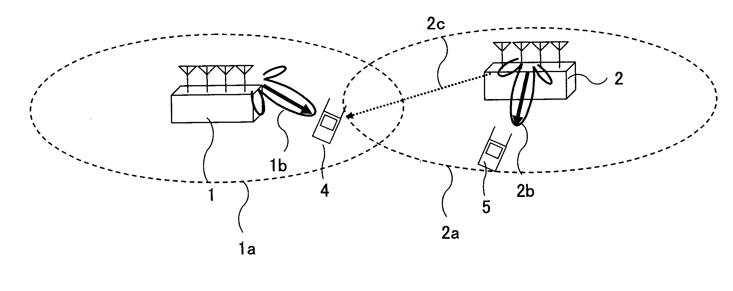
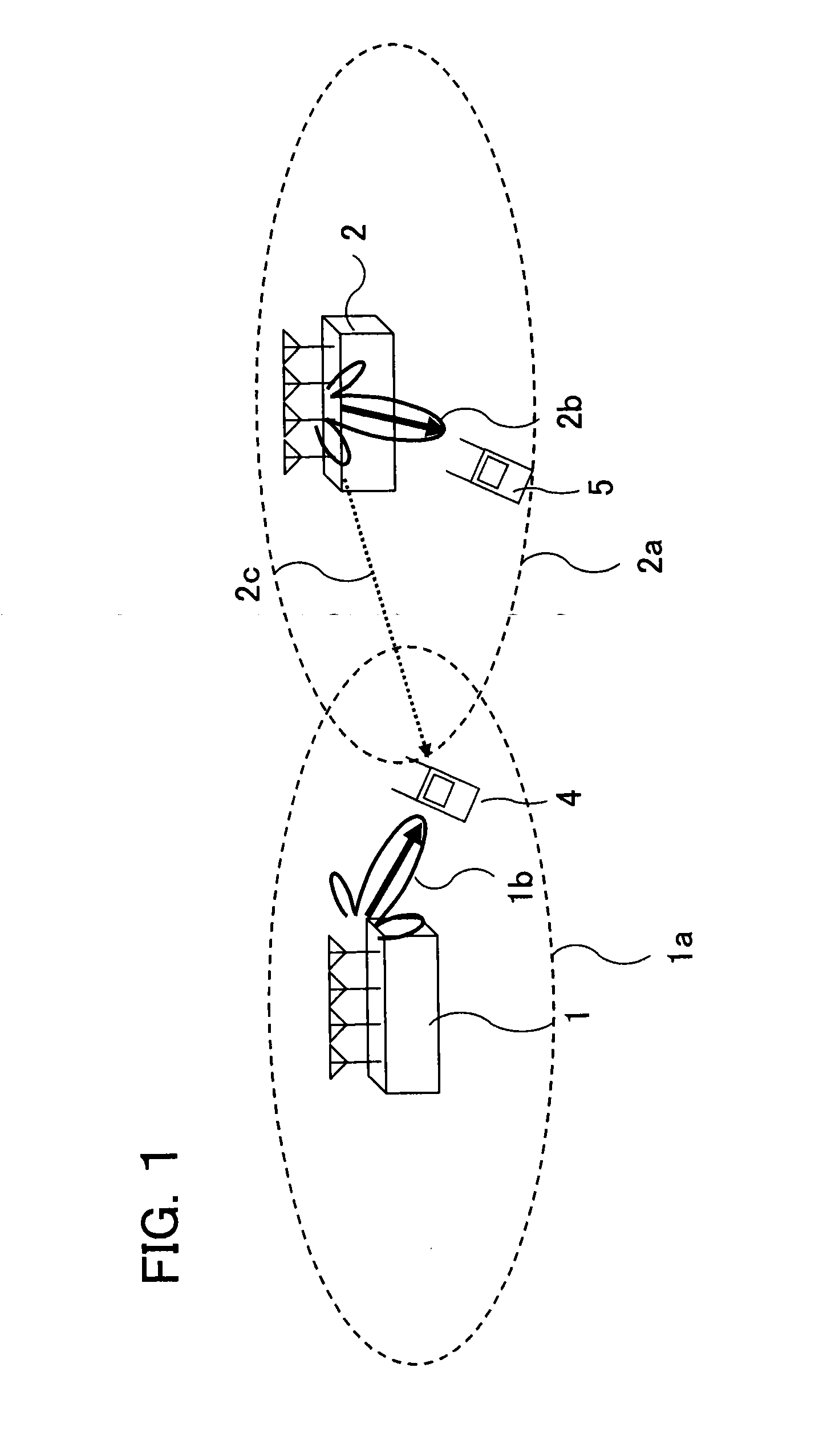
[0017]Let us assume that mobile terminals adapted for IRC are used in a radio communication system in which multiple radio base stations collaborate to adjust radio wave beams for controlling interfering radio wave beams received at mobile terminals with the use of IA or CS / CB described above. It is normally expected that interference suppression effects at the mobile terminals will be highly enhanced and reception quality will be improved in this case.

Problems solved by technology

However, radio base stations need not necessarily collaborate to control interfering radio wave beams for mobile terminals that can inherently ensure good reception quality by virtue of its high interference suppression capability by IRC.
Rather, if radio base stations collaborate to control interfering radio wave beams for such mobile terminals, it will be predicted that efficiency of processing in the overall radio communication system may be decreased.

Method used


Image

  • Radio communication system, radio base station, and mobile terminal
  • Radio communication system, radio base station, and mobile terminal
  • Radio communication system, radio base station, and mobile terminal

Examples


first embodiment

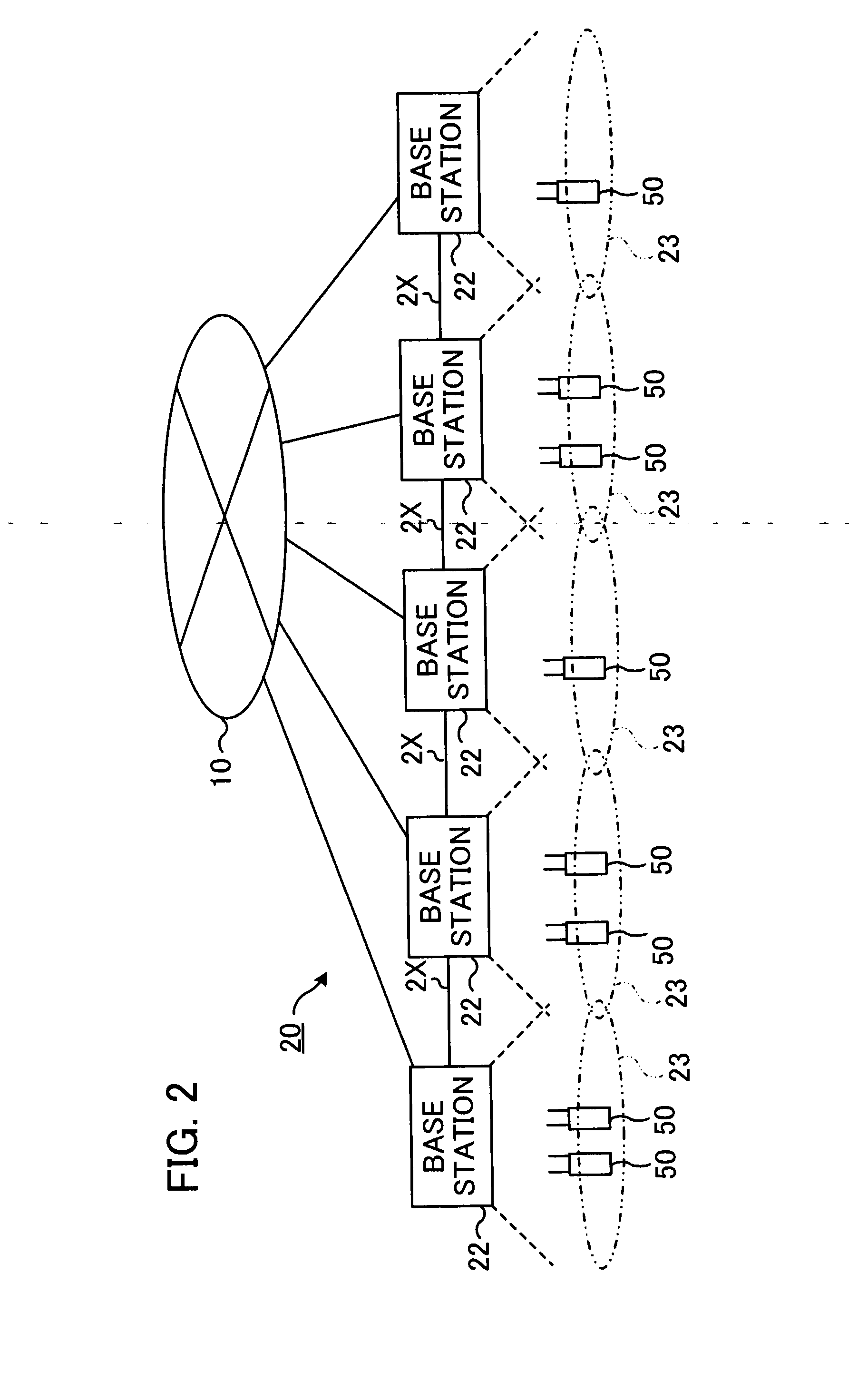
[0047]The radio communication system according to the first embodiment is related to interference alignment (IA) described above. FIG. 3 shows outline of downlink channel characteristics in the radio communication system. For the purpose of facilitating understanding, FIG. 3 shows only three radio base stations 22 (a first radio base station 221, a second radio base station 222, and a third radio base station 223) and five mobile terminals 50 (a first mobile terminal 501, a second mobile terminal 502, a third mobile terminal 503, a fourth mobile terminal 504, and a fifth mobile terminal 505).

[0048]The first mobile terminal 501 and the second mobile terminal 502 are located in the cell 231 of the first radio base station 221, and are connected to the first radio base station 221. The first radio base station 221 actually downlinks data signals to the first mobile terminal 501 and the second mobile terminal 502. The third mobile terminal 503 and the fourth mobile terminal 504 are loca...

second embodiment

[0099]In the first embodiment, interference-suppression-capability information of each mobile terminal 50 is shared in collaborating radio base stations 22, and the IA decider 28 of a radio base station 22 that is an interfering base station for a mobile terminal 50 decides whether or not IA should be executed for the mobile terminal 50.

[0100]However, another radio base station 22 that is the desired base station for a mobile terminal 50 may decide whether or not IA should be executed for the mobile terminal 50. A second embodiment will be described next. FIG. 8 shows the structure of a radio base station 22 according to the second embodiment. In the second embodiment, the structure and operation of the mobile terminal 50 may be the same as those of the first embodiment shown in FIG. 6.

[0101]In FIG. 8, the same reference symbols are used to identify elements commonly used in FIG. 7, and these elements will not be described in detail. As shown in FIG. 8, the radio base station 22 acc...

third embodiment

[0107]In the first and the second embodiments, the interference-suppression-capability calculator 62 of each mobile terminal 50 calculates the number A of interfering radio wave beams of which interference can be suppressed by the interference rejection combining processor 55 (the number of degrees of spatial freedom of the interference rejection combining processor 55). In addition, a signal (interference-suppression-capability information) indicating the number A of degrees of spatial freedom calculated by the interference-suppression-capability calculator 62 is supplied to the SC-FDMA modulator 70, and then is sent by radio to the radio base station 22 (desired radio base station) by means of the SC-FDMA modulator 70 and the radio transmitter 72.

[0108]However, each mobile terminal 50 may send, to its desired radio base station 22, interference-suppression-capability information indicating the number B of the reception antennas 52 of the mobile terminal 50, instead of interference...


PUM


Abstract

In a radio communication system including multiple mobile terminals and multiple radio base stations, the mobile terminal has a function of interference rejection combining. The radio base stations share downlink channel characteristics for mobile terminals connected to radio base stations. The radio base station gives weights to radio waves transmitted from multiple transmission antennas to perform in-phase addition of an interfering radio wave beam directed to a mobile terminal for which the desired radio base station is another radio base station to an interfering radio wave beam transmitted from yet another radio base station for limiting the number of interfering radio wave beams that arrive at the mobile terminal. The radio base station does not perform in-phase addition when the number of interfering radio wave beams of which interference can be suppressed by the mobile terminal is equal to or greater than the number of radio base stations that send interfering radio wave beams to the mobile terminal.

Description

FIELD OF THE INVENTION[0001]The present invention relates to a radio communication system, a radio base station, and a mobile terminal.BACKGROUND ART[0002]In the LTE (Long Term Evolution) Advanced of the 3GPP (Third Generation Partnership Project), OFDMA (Orthogonal Frequency Division Multiplexing Access) using MU-MIMO (multi-user multiple-input multiple-output) has been proposed. In MU-MIMO downlink transmission, a base station is able to not only communicate with multiple mobile terminals (UE, user equipments), but also to transmit different data streams (layers) simultaneously to a mobile terminal.[0003]In addition, in LTE Advanced, a reception technique for mobile terminals called “interference rejection combining” has been discussed. Interference rejection combining (IRC) is a technique for downlink communication, in which a mobile terminal gives weights to signals obtained by reception antennas so as to suppress interference with the desired radio wave beam from the visited ba...

Claims


Application Information

Patent Timeline
Patent Type & Authority Applications(United States)
IPC IPC(8): H04B1/62H04W72/08
CPCH04W72/082H04B1/62H04W16/28H04W24/10H04W28/16H04B7/0617H04B7/024H04B7/0452H04B7/0626H04B7/0628H04B7/0645H04B7/0854H04J11/005H04W72/541
Inventor SANO, YOUSUKEOHWATARI, YUSUKEMIKI, NOBUHIKOMORIMOTO, AKIHITOOKUMURA, YUKIHIKO
Owner NTT DOCOMO INC
Why Eureka
Try Eureka