Projection system, image processing device, and projection method

a projection system and image processing technology, applied in the direction of static indicating devices, instruments, panoramic photography, etc., can solve the problems of reducing convenience, difficult to take an image, and difficult to secure a sufficient distance for taking an imag

Active Publication Date: 2015-01-29
RICOH KK
View PDF34 Cites 45 Cited by
  • Summary
  • Abstract
  • Description
  • Claims
  • Application Information

AI Technical Summary

Problems solved by technology

Therefore, this technology has been unsatisfactory in that equipment such as a tripod is necessary, which reduces the convenience.
Furthermore, if the number of projectors increases, there have been cases where it is difficult to take an image to include the projection ranges of all projectors in the angular field at once.
For example, when multi-projection is performed on the wall of a hallway, due to restrictions such as the width of the hallway, it is difficult to secure a sufficient distance for taking an image by including the projection ranges of all projectors in the angular field.
In this case, when the patterns of the different projectors adhere to each other, it is difficult to separate the patterns and determine the attribution of the patterns.
Therefore, the conventional technology has been unsatisfactory.
Therefore, the conventional technology of split imaging described in Patent Document 2 has been unsatisfactory in terms of the ease in calibration and cost.
Furthermore, the problem of the structure patterns overlapping each other is not addre

Method used


Image

  • Projection system, image processing device, and projection method
  • Projection system, image processing device, and projection method
  • Projection system, image processing device, and projection method

Examples


Embodiment Construction

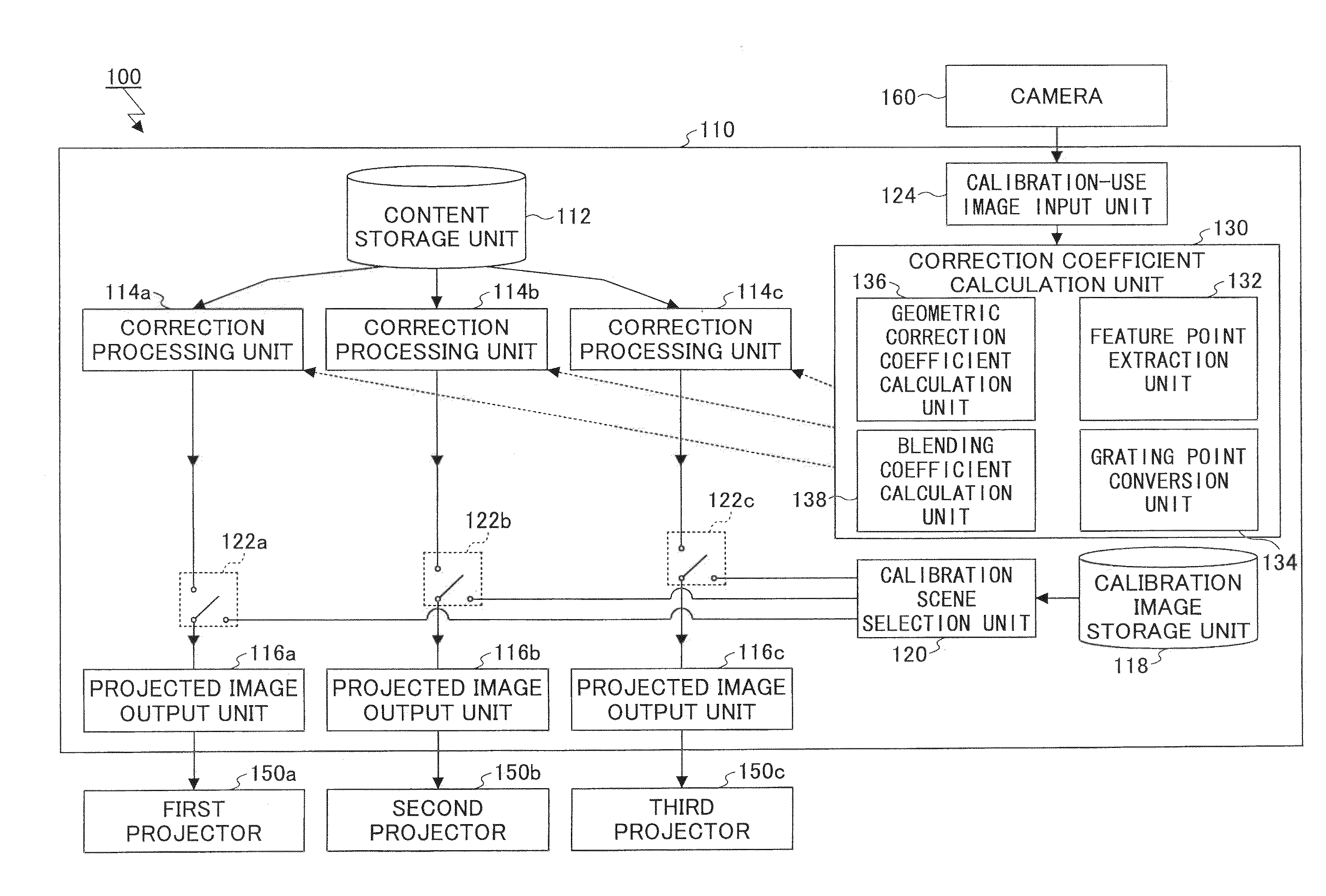
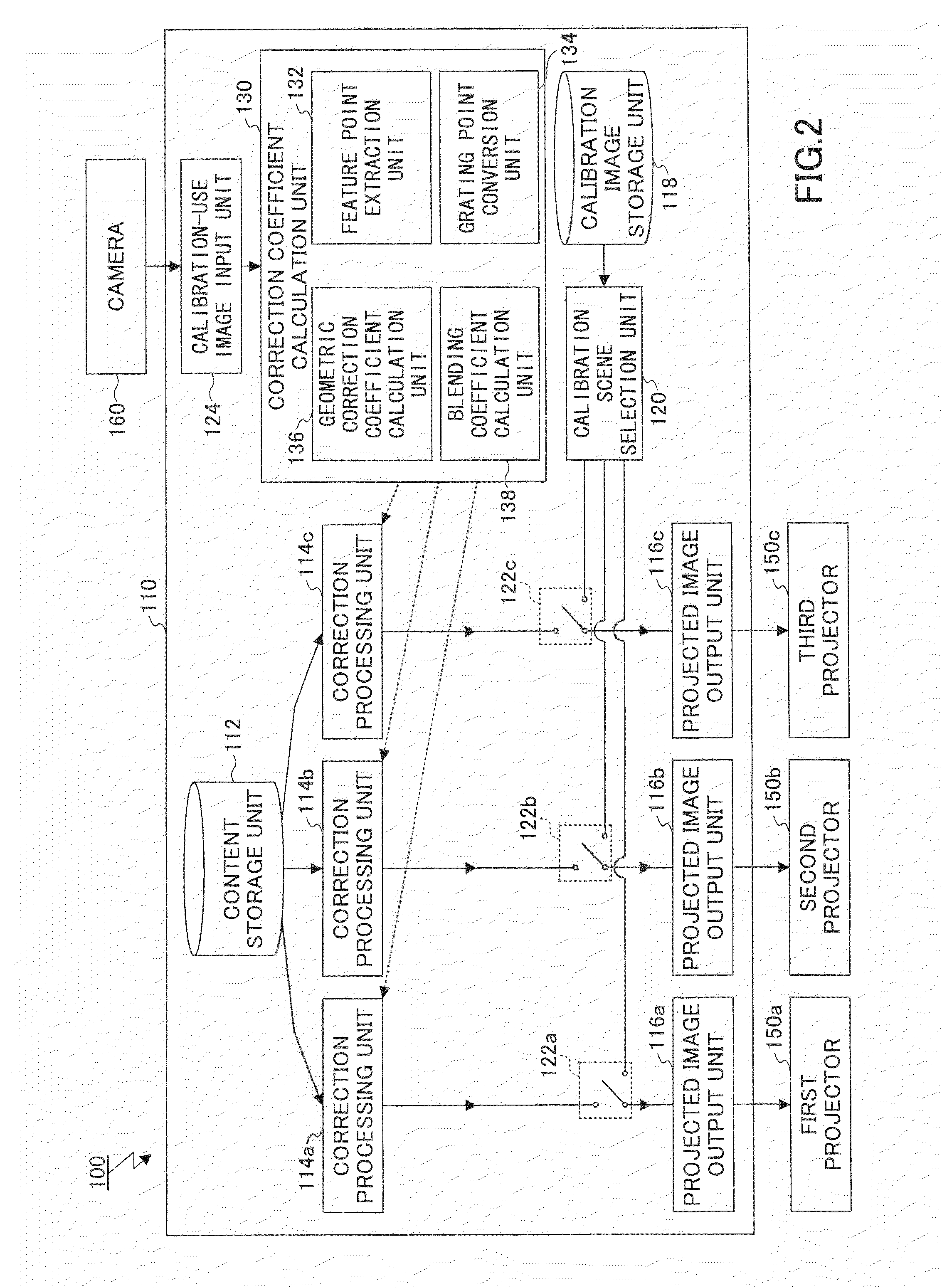
[0046]A description is given, with reference to the accompanying drawings; however, the present invention is not limited to the embodiments described below. Note that in the embodiments described below, an example of a projection system is described by a projection system 100 including a plurality of projectors which are projection units, a single camera which is an imaging unit, and an image processing device which performs overall control.

Overall Configuration

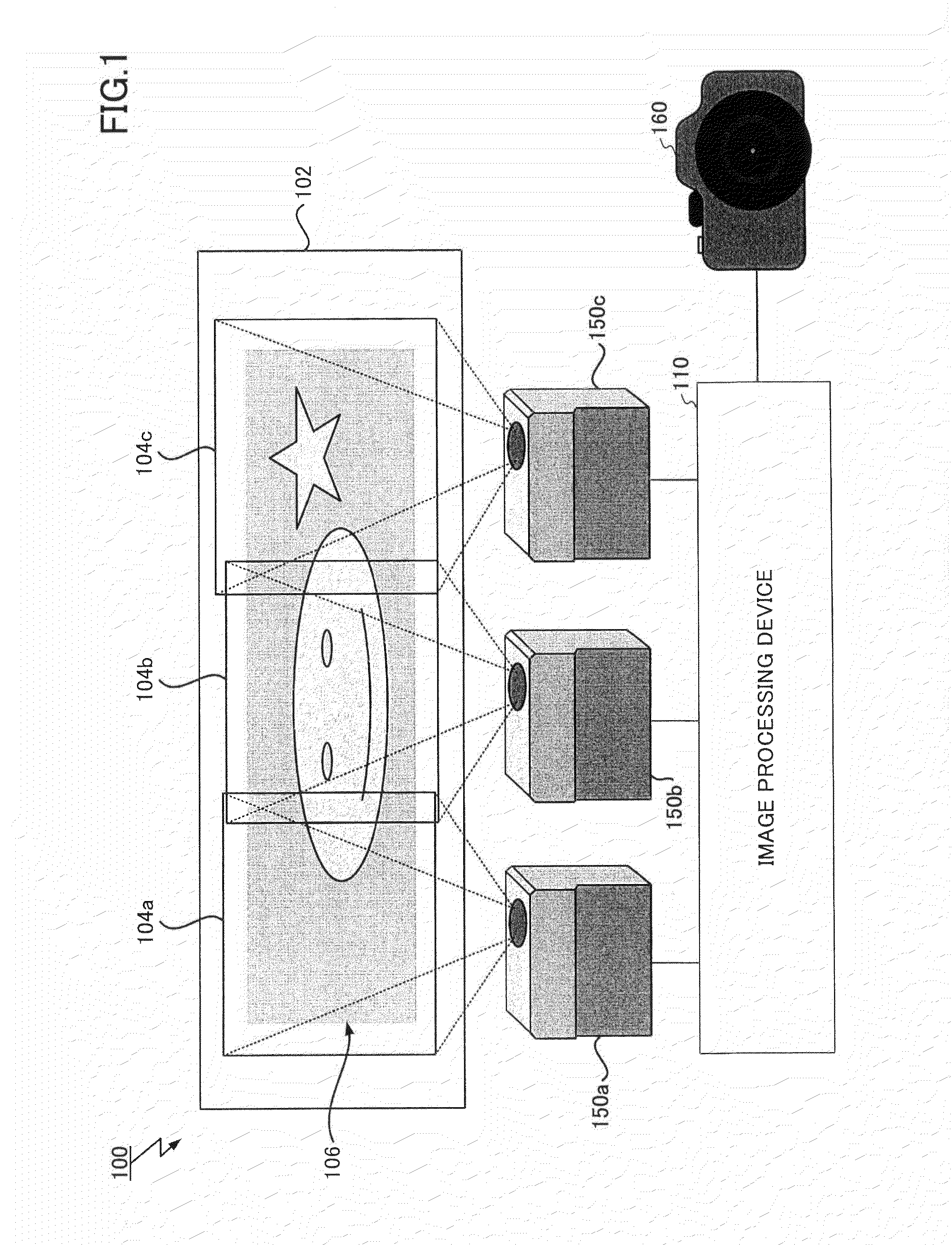
[0047]FIG. 1 is a schematic diagram illustrating the overall configuration of the projection system 100 according to the present embodiment. The projection system 100 illustrated in FIG. 1 includes an image processing device 110 for performing the overall control of the system, a plurality of projectors 150, and a camera 160. Note that in the embodiment described below, the projection system 100 has a configuration corresponding to so called large-sized screen multi-projection, in which the projected images of three projector...


PUM


Abstract

A projection system includes projection units configured to project an image on a projection body; a preparing unit configured to prepare calibration-use images; an extraction unit configured to extract, from each of the calibration-use images, at least grating points indicating a distortion in a projected image of one of the projection units and alignment points of the projected image of the one of the projection units or another one of the projection units; a conversion unit configured to convert, onto a common coordinate system, the grating points of the projected images of the projection units extracted from the calibration-use images, based on alignment points common to the calibration-use images; and a geometric correction coefficient calculation unit configured to calculate a geometric correction coefficient for providing a projection image to be projected from the projection units, based on the grating points on the common coordinate system.

Description

BACKGROUND OF THE INVENTION[0001]1. Field of the Invention[0002]The present invention relates to a projection system, an image processing device, and a projection method. More specifically, the present invention relates to a projection system for projecting an image on a projection body by a plurality of projection units, an image processing device constituting the projection system, and a projection method executed by the projection system.[0003]2. Description of the Related Art[0004]Conventionally, the multi-projection technology is garnering attention, in which projected images from a plurality of projectors are arranged with areas overlapping with each other, and a single high-resolution image is projected on a screen.[0005]A known example of the above multi-projection technology is described in Japanese Patent No. 3908255 (Patent Document 1). In the image projection system of Patent Document 1, a reference image is projected onto a screen from the respective projectors. The ref...

Claims


Application Information

Patent Timeline
IPC IPC(8): G06T7/00G06K9/46G03B21/14G06V10/145
CPCG06T7/0028G03B21/142G06K9/4676G06T3/005G03B21/13G03B37/04G06T7/33H04N9/3194H04N9/3147H04N9/3185G06V10/145G06V10/754H04N9/3188G09G5/00
Inventor ISHIKAWA, MASAAKIUCHIYAMA, YUKINAKA
Owner RICOH KK
Why Eureka
Try Eureka