
Transport device with linear-motor drive

a technology of linear motors and transportation devices, applied in transportation and packaging, locomotives, conveyors, etc., can solve problems such as curved sections and particularly difficult to achieve the effect of curved sections

Active Publication Date: 2015-01-29
BECKHOFF AUTOMATION GMBH
View PDF3 Cites 15 Cited by
  • Summary
  • Abstract
  • Description
  • Claims
  • Application Information

AI Technical Summary

Benefits of technology

The present invention provides a transport device that is easy to access, has a simple structure, and ensures secure guidance of the carriage around the guide rail as it is driven by the linear-motor drive device. The carriage can be stiffly supported as it moves along the guide rail, and it is easy to replace and maintain each carriage. The guide surfaces of each side wall are angled at an angle of substantially 90° to each other, which allows for reliable guidance of the carriage in almost any imaginable travel situation.

Problems solved by technology

Because the guide rail is configured as a closed, endless circuit, problems occur particularly in the area of the curved sections as a result of the high frictional and inertial forces of the running rollers on the guide rail and as a result of the partly present play between the running rollers and the guide rail.

Method used


Image

  • Transport device with linear-motor drive
  • Transport device with linear-motor drive
  • Transport device with linear-motor drive

Examples


Embodiment Construction

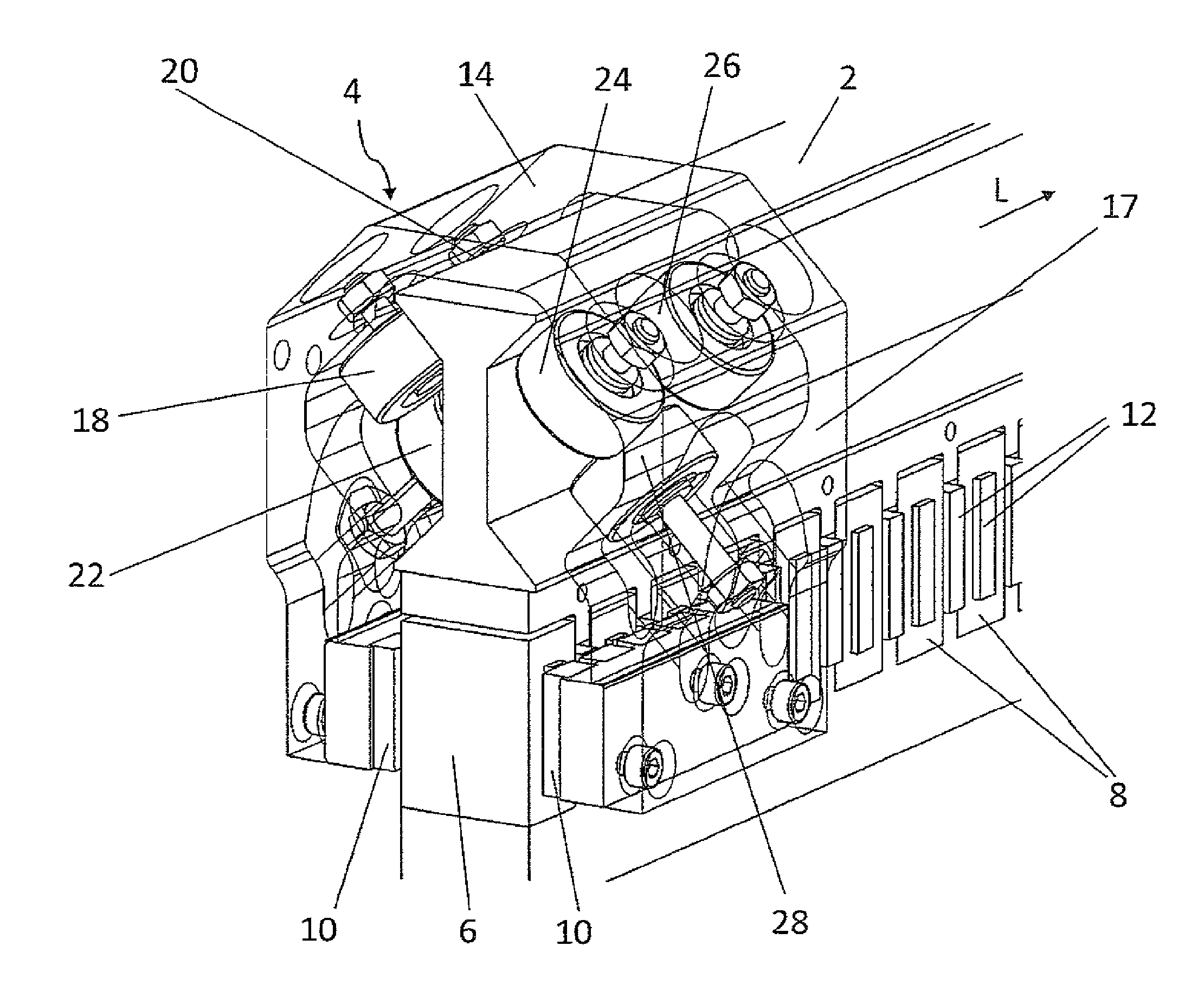
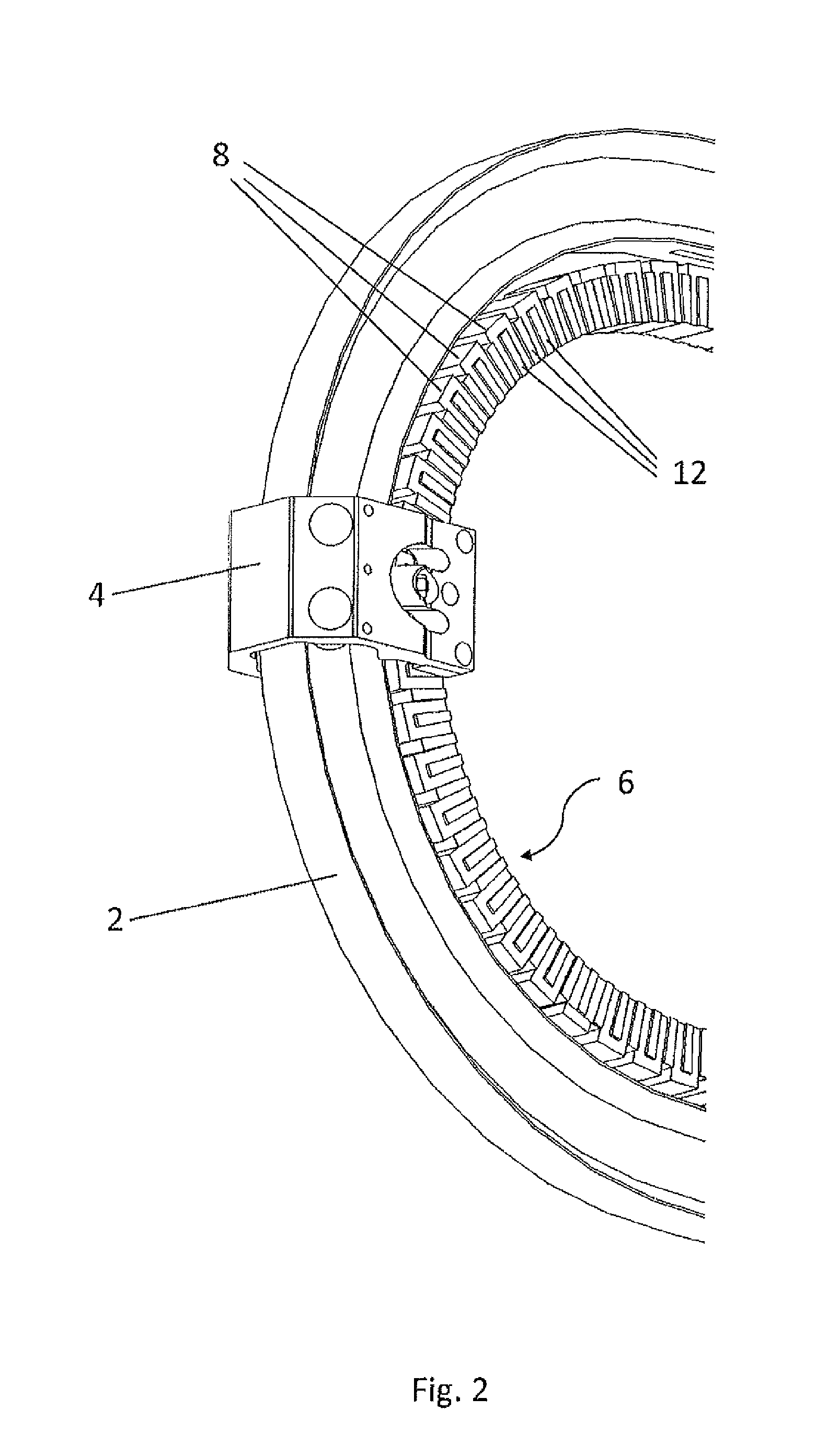
[0024]FIG. 1 shows one possibility for the basic structure of a transport device according to the invention for conveying products. The transport device comprises a stationary, endless guide rail 2 for guiding at least one movable carriage 4, which serves to convey a product and is moved along the guide rail 2. Even though only one carriage 4 is present in the exemplary case shown here, several carriages 4 will usually be moving around the same guide rail 2 at the same time. The material of the guide rail 2 and of the carriage 4 is preferably aluminum.

[0025]A linear-motor drive device 6, which is usually configured as an array of motor coils, is used to drive the at least one carriage 4. The linear-motor drive device 6 comprises many coils 8 arranged in a row (see FIG. 2), preferably of copper, which can be supplied individually with current. The carriages 4, as can be seen in FIGS. 3 and 4, comprise in turn at least two permanent magnets 10, which interact with the linear-motor dri...


PUM


Abstract

The transport device for conveying products has several symmetrically configured, movable carriages having inverted U-shape, each carriage having permanent magnets, also has an endless guide rail for guiding the carriages and a linear-motor drive device to drive the carriages. Each symmetric half of each carriage has three running rollers projecting inwardly from sidepieces of the carriage. The three running rollers of the first half rest on first and second guide surfaces on a first side wall of the guide rail, and the three running rollers of the second half rest on first and second guide surfaces on the second side wall of the guide rail. Each guide surface is arranged at an acute angle to a longitudinal center plane of the transport device, and the two guide surfaces of each side wall are at an angle of 80° to 100° to each other.

Description

RELATED APPLICATIONS[0001]The present patent application claims the benefit of priority to the following applications, and is a continuation of PCT Application No. PCT / EP2013 / 053258 filed Feb. 19, 2013, which claims priority to German Patent Application No. DE 102012103378.1, filed Apr. 18, 2012, the entire contents of each of which are incorporated herein by reference.FIELD AND BACKGROUND OF THE INVENTION[0002]The present invention relates to a transport device with linear motor drive.[0003]Transport devices of this type have already been known for a long time and offer the advantage that the carriages or conveyor elements moved by the linear motor drive can be moved independently of each other, which results in considerable advantages over conventional mechanical transport devices.[0004]One of the purposes served by these types of transport devices is to be found in, for example, the loading of packaging machines with products as known from U.S. Pat. No. 6,876,896 B1, for example,...

Claims


Application Information

Patent Timeline
IPC IPC(8): B60L13/03B61B13/00B61B13/04B61C3/00
CPCB60L13/03B61B13/04B61B13/00B61C3/00B65G54/02B65G2812/99
Inventor AUMANN, THOMASRIEKENBRAUCK, JOERGKRAHL, WOLFGANGLINKE, ROBERTO
Owner BECKHOFF AUTOMATION GMBH
Learn More