Single-layer capacitive touch sensor

a capacitive touch sensor, single-layer technology, applied in the field of capacitive touch sensors, can solve the problems of increasing the power consumption of the whole device, reducing the conductivity of thin film electrodes, and reducing the light transmittance of resistive touch sensors with the accumulation of usage time and frequency, so as to improve the touch experience of users, reduce the area of dead zones, and improve the effect of sensing efficiency

Active Publication Date: 2015-01-22
PIXART IMAGING INC
View PDF2 Cites 8 Cited by
  • Summary
  • Abstract
  • Description
  • Claims
  • Application Information

AI Technical Summary

Benefits of technology

The present invention provides a single-layer capacitive touch sensor that reduces dead zones and optimizes each sensing unit to improve sensing efficiency. Additionally, the sensor's structure improves light transmittance, reduces thickness, and reduces manufacturing costs. These improvements enhance the user's touch experience and improve the overall quality of the touch sensor.

Problems solved by technology

Nevertheless, the light transmittance of the resistive touch sensor can degrade with the accumulation of usage time and frequencies of the product.
Especially the abrasion is caused at specific areas such as frequent touched positions thereby reducing the conductivity of the thin film electrodes.
In addition, in order to compensate for the disadvantage due to the low-transmittance material, a stronger backlight will be applied such that the power consumption of the whole device is increased as well.
However, the conventional capacitive touch sensor is designed with at least 3 layers (e.g. an x-axis sensing layer, a y-axis sensing layer and a shielding layer) and more complex control ICs thereby having problems of reduced transmittance, increased thickness and high cost.
Therefore, the trace area outside the sensing electrode ES and the driving electrode ED cannot be utilized efficiently to have the problem of dead zones being formed in the areas with traces.

Method used


Image

  • Single-layer capacitive touch sensor
  • Single-layer capacitive touch sensor
  • Single-layer capacitive touch sensor

Examples


first embodiment

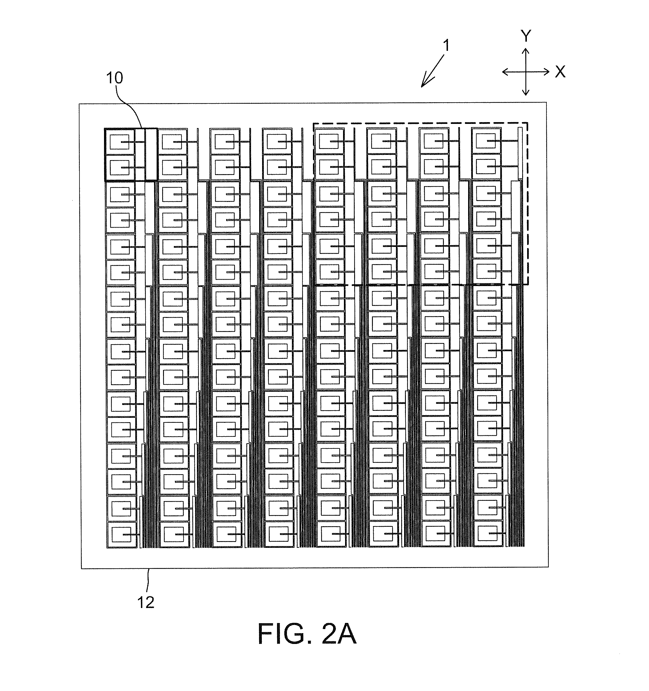
[0032]FIG. 2A is a schematic diagram of a single-layer capacitive touch sensor 1 according to the present disclosure. The touch sensor 1 includes a plurality of sensing units 10, and the sensing units 10 are arranged in a matrix on a substrate 12. A user (not shown) may contact with the sensing units 10 through a finger or a touch pen to generate an induced capacitance. And a control IC (not shown) may generate a position signal according to the induced capacitance to a host to accomplish a corresponding action or perform a predetermined command.

[0033]It should be mentioned that since a touch sensor may be attached to a display device to be operated by a user, the sensing units 10 of the touch sensor 1 are preferably arranged as a rectangle to match the shape of the display device, but the present disclosure is not limited thereto. The arrangement of the sensing units 10 may be determined according to the shape of different display devices.

[0034]Please referring to FIGS. 2A and 2B a...

second embodiment

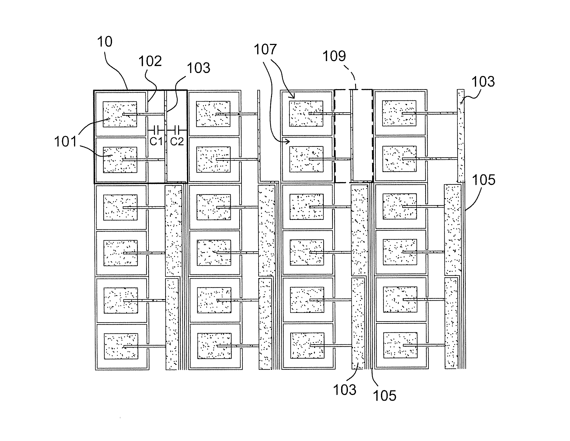
[0039]Please referring to FIGS. 3A and 3B at the same time, FIG. 3A is a schematic diagram of a single-layer capacitive touch sensor 1 according to the present disclosure; and FIG. 3B is a partially enlarged diagram of the region within the dotted line in FIG. 3A. The touch sensor 1 includes a plurality of first sensing units 10A and a plurality of second sensing units 10B arranged in a matrix on a substrate 12, wherein the sensing units including at least one trace 105 are referred to the second sensing units 10B. Each of the first sensing units 10A and each of the second sensing units 10B both have at least a first electrode 101 (two first electrodes being shown herein), a second electrode 102 and a third electrode 103, wherein the second electrode 102 is arranged in a ring shape as well and electrically isolated from the two first electrodes 101, and the first electrodes 101 are located in an interior space 107 of the ring and configured to form a mutual capacitance between the f...


PUM


Abstract

There is provided a single-layer capacitive touch sensor including a plurality of sensing units arranged in a matrix on a substrate. Each of the sensing units has a Out electrode, a second electrode and a third electrode. The second electrode is arranged in a ring shape and electrically isolated from the first electrode, and the first electrode is located in an interior space of the ring shape. The third electrode is arranged outside of the interior space and electrically connected to the first electrode, wherein the second electrode of at least a part of the sensing units is configured to respectively form a mutual capacitance with the third electrode of two adjacent sensing units.

Description

RELATED APPLICATIONS[0001]The present application is based on and claims priority to Taiwanese Application Number 102125675, filed Jul. 17, 2013, the disclosure of which is hereby incorporated by reference herein in its entirety.BACKGROUND[0002]1. Field of the Disclosure[0003]This disclosure generally relates to a touch sensor and, more particularly, to a single-layer capacitive touch sensor with reduced dead zones.[0004]2. Description of the Related Art[0005]The conventional touch sensor, for example a resistive touch sensor generally includes a two-layer structure (e.g. thin film electrodes) and a steady voltage is applied thereto. Spacers are inserted between the two layers to isolate the two layers from each other. When a user applies a pressure through a finger or a touch pen to a position on the two-layer structure, the two-layer structure is electrically conducted (i.e. short) at the position. Therefore, a control IC may calculate the position contacted by the user according ...

Claims


Application Information

Patent Timeline
IPC IPC(8): G06F3/044
CPCG06F3/044G06F2203/04111G06F3/0443G06F3/0448
Inventor YANG, KUAN-YI
Owner PIXART IMAGING INC
Why Eureka
Try Eureka