Vibrating Mirror Element, Distance Measuring Apparatus, and Projector

a technology of mirror element and distance measuring apparatus, which is applied in the direction of optical radiation measurement, instruments, and using reradiation, can solve the disadvantageous limitation of the period of time when the turning angle velocity of the first movable element can be substantially constant, and achieve the effect of easy oscillation and easy formation

Inactive Publication Date: 2015-01-22
FUNAI ELECTRIC CO LTD
View PDF8 Cites 12 Cited by
  • Summary
  • Abstract
  • Description
  • Claims
  • Application Information

AI Technical Summary

Benefits of technology

[0009]In the vibrating mirror element according to the first aspect of the present invention, as hereinabove described, the driving of the resonant drive portion is controlled to oscillate the mirror portion about the axis at the resonance frequency, and the driving of the correction drive portion is controlled to keep the turning angle velocity of the mirror portion substantially constant by oscillating the mirror portion about the axis at the non-resonance frequency in the direction opposite to the direction in which the resonant drive portion oscillates the mirror portion, whereby the driving of the correction drive portion can be controlled to oscillate the mirror portion at the arbitrary non-resonance frequency unlike the case where the driving of the correction drive portion is controlled to vibrate the mirror portion at the resonance frequency and a frequency of an even multiple of the resonance frequency, and hence the degree of freedom of control of the correction drive portion can be increased. Consequently, the turning angle velocity of the mirror portion can be kept substantially constant during a substantially entire period in one cycle of the oscillation. Furthermore, in the case where a vibrating mirror element in which the turning angle velocity is not constant is applied to a distance measuring apparatus, for example, a laser light source must be pulse-driven in order to emit laser light at a regular angular interval, and the pulse-drive timing must be temporally corrected. On the other hand, according to the present invention, the turning angle velocity of the mirror portion can be kept substantially constant during the substantially entire period in one cycle of the oscillation, and hence a distance measuring apparatus requires no control means configured to perform pulse control on laser light, so that the structure of the distance measuring apparatus can be simplified.
[0032]In the projector according to the third aspect of the present invention, as hereinabove described, the driving of the resonant drive portion is controlled to oscillate the mirror portion about the axis at the resonance frequency, and the driving of the correction drive portion is controlled to keep the turning angle velocity of the mirror portion substantially constant by oscillating the mirror portion about the axis at the non-resonance frequency in the direction opposite to the direction in which the resonant drive portion oscillates the mirror portion, whereby the driving of the correction drive portion can be controlled to oscillate the mirror portion at the arbitrary non-resonance frequency unlike the case where the driving of the correction drive portion is controlled to vibrate the mirror portion at the resonance frequency and a frequency of an even multiple of the resonance frequency, and hence the degree of freedom of control of the correction drive portion can be increased. Consequently, the projector in which the turning angle velocity of the mirror portion can be kept substantially constant during a substantially entire period in one cycle of the oscillation can be provided.

Problems solved by technology

In the resonance type light-deflector disclosed in Japanese Patent Laying-Open No. 2008-009446, however, the period of time when the turning angle velocity of the first movable element can be substantially constant is disadvantageously limited whereas the first movable element is configured such that the turning angle velocity is substantially constant during the prescribed period of time in one cycle of the oscillation.

Method used


Image

  • Vibrating Mirror Element, Distance Measuring Apparatus, and Projector
  • Vibrating Mirror Element, Distance Measuring Apparatus, and Projector
  • Vibrating Mirror Element, Distance Measuring Apparatus, and Projector

Examples


first embodiment

[0044]The structure of a distance measuring apparatus 100 according to a first embodiment of the present invention is now described with reference to FIGS. 1 to 6.

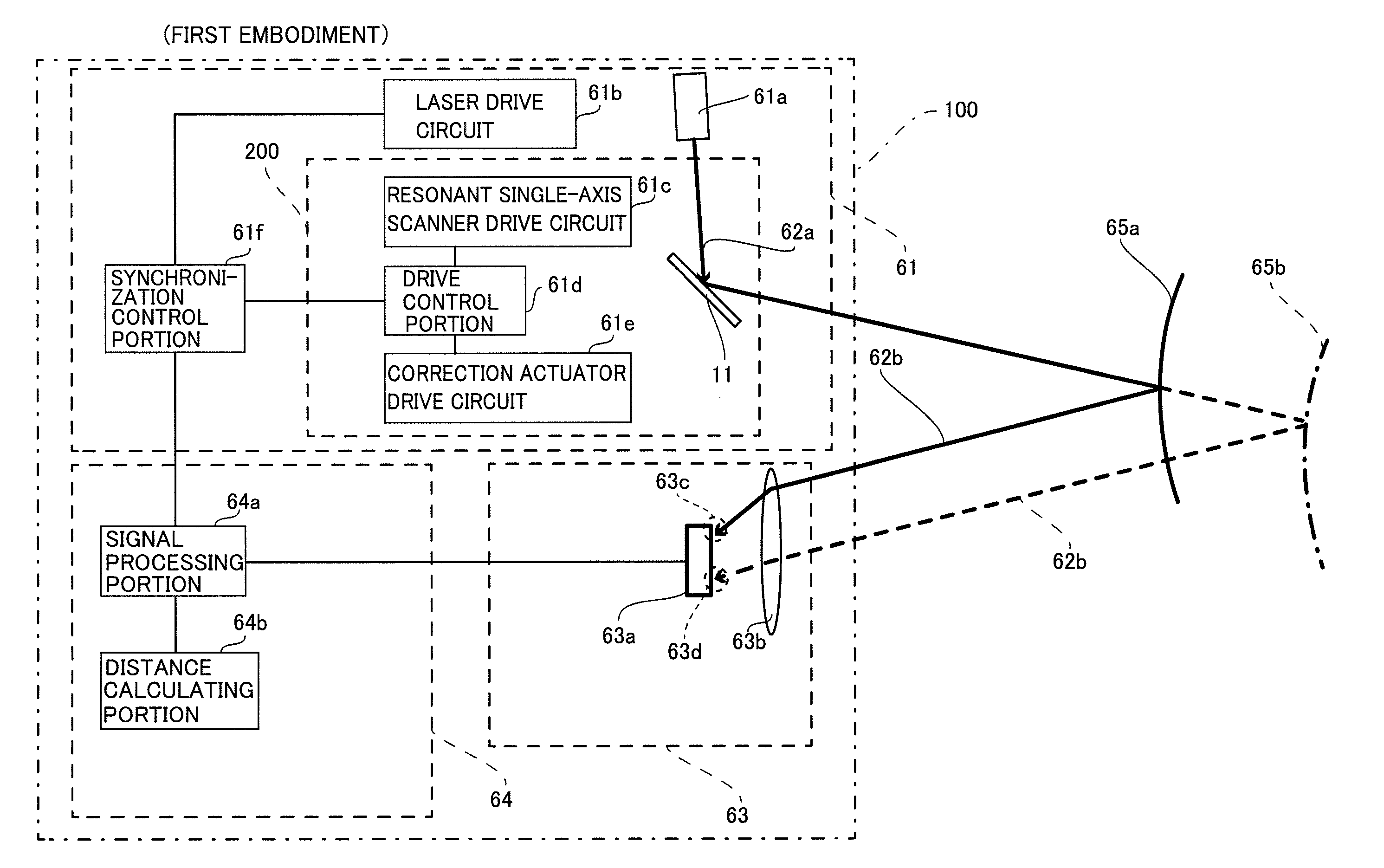
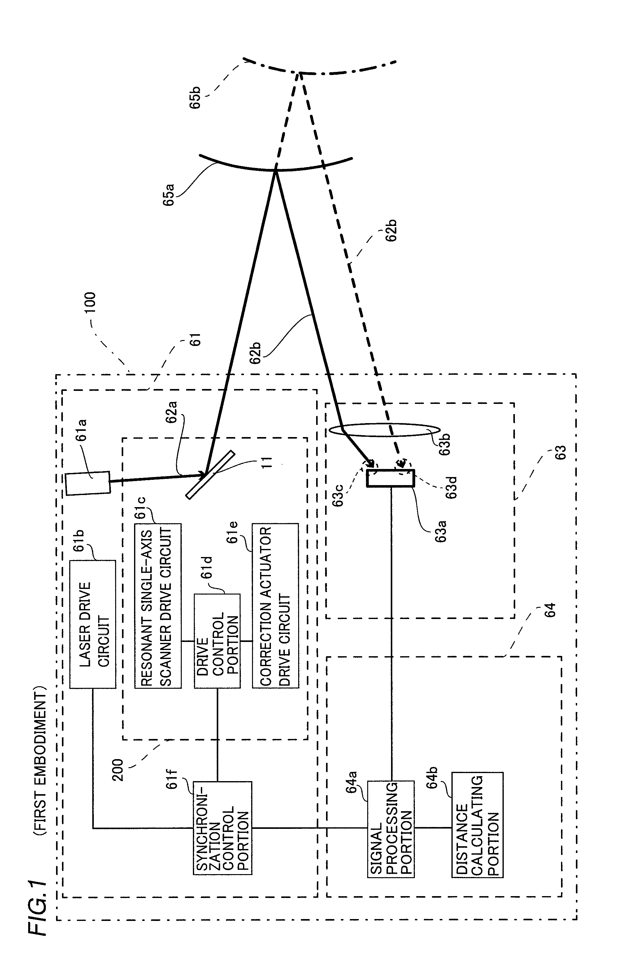
[0045]The distance measuring apparatus 100 according to the first embodiment of the present invention includes a light emitting portion 61, a light receiving portion 63 receiving laser light 62a emitted from the light emitting portion 61 and reflected by an measurement object 65a, and a distance measuring portion 64 acquiring a distance from the measurement object 65a on the basis of the detection result of the light receiving portion 63, as shown in FIG. 1.

[0046]The light emitting portion 61 includes a CW (continuous wave) laser light source 61a emitting the laser light 62a of an infrared wavelength region, a laser drive circuit 61b configured to drive the CW laser light source 61a, a vibrating mirror element 200 configured to deflect the laser light 62a emitted from the CW laser light source 61a, and a synchronization co...

second embodiment

[0083]The structure of a distance measuring apparatus 101 according to a second embodiment is now described with reference to FIG. 7. According to the second embodiment, the distance measuring apparatus 101 is configured to include a short-pulse laser light source and a distance measuring portion detecting light receiving time information by a light receiving portion, calculating a distance between the distance measuring apparatus and a measurement object from the detection result, unlike the aforementioned distance measuring apparatus 100 according to the first embodiment configured to include the CW laser light source and the distance measuring portion detecting light receiving position information, calculating the distance between the distance measuring apparatus and the measurement object from the detection result.

[0084]As shown in FIG. 7, the distance measuring apparatus 101 includes a light emitting portion 61g, a light receiving portion 63e receiving short-pulse laser light 6...

third embodiment

[0089]The structure of a projector 102 according to a third embodiment is now described with reference to FIG. 8. In the third embodiment, the vibrating mirror element according to the present invention is applied to the projector, unlike in each of the aforementioned first and second embodiments in which the vibrating mirror element according to the present invention is applied to the distance measuring apparatus.

[0090]As shown in FIG. 8, no light receiving portion 63 or distance measuring portion 64 is provided in the projector 102 according to the third embodiment, unlike in the aforementioned first embodiment. According to the third embodiment, a vibrating mirror element 201 includes at least two vibrating mirror elements 200 or is configured to be biaxially driven in order to deflect laser light 62a in a planar direction (an X-axis or Y-axis direction). The remaining structure of the projector 102 according to the third embodiment is similar to that of the distance measuring ap...


PUM


Abstract

A vibrating mirror element includes a drive control portion configured to control the driving of a correction drive portion to keep the turning angle velocity of a mirror portion substantially constant by oscillating the mirror portion about an axis at a non-resonance frequency in a direction opposite to a direction in which a resonant drive portion oscillates the mirror portion.

Description

BACKGROUND OF THE INVENTION[0001]1. Field of the Invention[0002]The present invention relates to a vibrating mirror element, a distance measuring apparatus, and a projector, and more particularly, it relates to a vibrating mirror element, a distance measuring apparatus, and a projector each including a resonant drive portion and a drive control portion controlling the driving of the resonant drive portion.[0003]2. Description of the Background Art[0004]A vibrating mirror element, a distance measuring apparatus, and a projector each including a resonant drive portion and a drive control portion controlling the driving of the resonant drive portion are known in general, as disclosed in Japanese Patent Laying-Open No. 2008-009446.[0005]Japanese Patent Laying-Open No. 2008-009446 discloses an image-forming apparatus having a resonance type light-deflector (vibrating mirror element) for deflecting a laser light, a driving portion (resonant drive portion) for oscillating a first movable e...

Claims


Application Information

Patent Timeline
Patent Type & Authority Applications(United States)
IPC IPC(8): G01B11/14G02B26/10G01S17/10
CPCG01B11/14G02B26/105G01B11/026G01S7/4817G01S17/10G01S17/42G01S17/48G02B26/0858G02B26/101
Inventor MURAYAMA, MANABU
Owner FUNAI ELECTRIC CO LTD
Why Eureka
Try Eureka