
Stop control apparatus for internal combustion engine

Active Publication Date: 2015-01-22
TOYOTA JIDOSHA KK
View PDF2 Cites 6 Cited by
  • Summary
  • Abstract
  • Description
  • Claims
  • Application Information

AI Technical Summary

Benefits of technology

The invention relates to a control system for an internal combustion engine that reduces vibration during start-up. By controlling the throttle opening degree and adjusting torque, the system reduces negative pressure in the intake and increases it in the compression stroke, which helps to stop the crank angle in a position that reduces vibration. The control system calculates the adjusting torque based on the crank angle, and takes into account the difference in the number of revolutions of the motor to control the crank angle with higher accuracy when the engine stops. This technology also allows for more accurate control of the piston position, which helps to improve fuel efficiency and reduce emissions.

Problems solved by technology

In the case of a three-or-less cylinder internal combustion engine, however, since there can be a time in which none of the cylinders is in the intake stroke, the braking effect due to the intake negative pressure does not become constant, and the crank angle is hardly controlled.
In other words, in the technologies described in the Patent documents 1 to 3 described above, there is such a technical problem that it is likely difficult to control the crank angle due to the generation of the intake negative pressure.

Method used


Image

  • Stop control apparatus for internal combustion engine
  • Stop control apparatus for internal combustion engine
  • Stop control apparatus for internal combustion engine

Examples


Embodiment Construction

[0049]Hereinafter, an embodiment of the present invention will be explained with reference to the drawings.

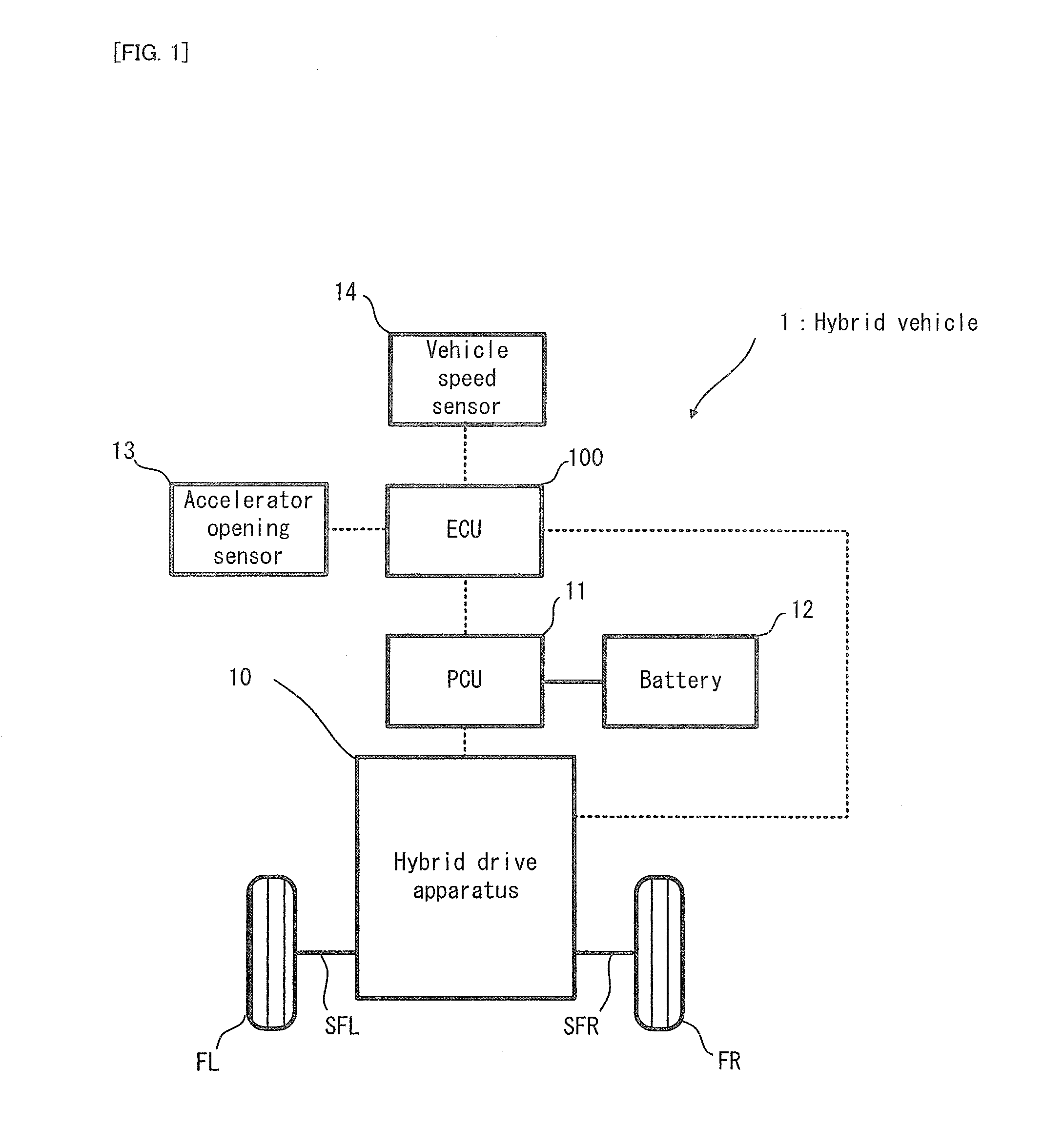
[0050]Firstly, an entire configuration of a hybrid vehicle in which a stop control apparatus for an internal combustion engine in the embodiment is installed will be explained with reference to FIG. 1. FIG. 1 is a schematic configuration diagram conceptually illustrating the configuration of the hybrid vehicle.

[0051]In FIG. 1, a hybrid vehicle 1 in the embodiment is provided with a hybrid drive apparatus 10, a power control unit (PCU) 11, a battery 12, an accelerator opening sensor 13, a vehicle speed sensor 14, and an ECU 100.

[0052]The ECU 100 is one example of the “stop control apparatus for the internal combustion engine” of the present invention. The ECU 100 is provided with a central processing unit (CPU), a read only memory (ROM), a random access memory (RAM), and the like. The ECU 100 is an electronic control unit configured to control the operation of each unit of the h...


PUM


Abstract

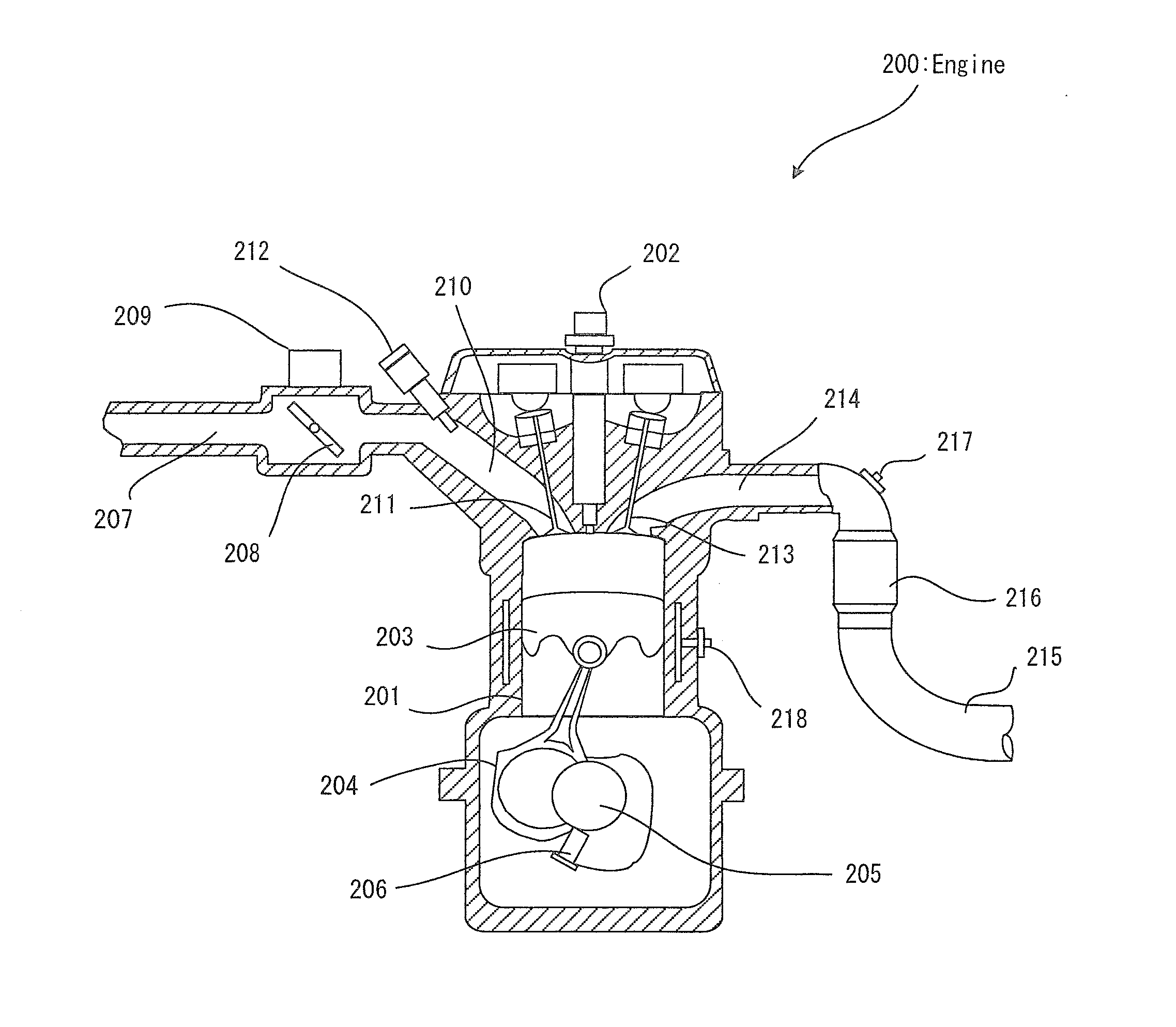
A stop control apparatus (100) for an internal combustion engine performs stop control of a three-or-less cylinder internal combustion engine (200). The stop control apparatus for the internal combustion engine is provided with: a determining device (161) configured to determine a compression stroke immediately before the internal combustion engine stops; and a throttle valve controlling device (168) configured to control an opening degree of a throttle valve (208) to be a predetermined opening degree while an intake valve (211) is closed in all cylinders, in the compression stroke immediately before the internal combustion engine stops, which is determined by the determining device. This reduces an influence of an intake negative pressure in an intake stroke, and makes it possible to preferably control the crank angle when the engine stops, even in the three-or-less cylinder internal combustion engine.

Description

TECHNICAL FIELD[0001]The present invention relates to a stop control apparatus for an internal combustion engine configured to control a stop operation of the internal combustion engine installed in a vehicle such as, for example, an automobile.BACKGROUND ART[0002]This type of internal combustion engine is required to perform such control that a crank angle when the engine stops is within a predetermined range, for example, in order to suppress vibration when starting the engine. For the control of the crank angle, for example, a method of increasing a throttle opening degree immediately before the internal combustion engine stops is used. For example, it is proposed in Patent document 1 that the variation of the crank angle when the engine stops is reduced by increasing the throttle opening degree in an intake stroke immediately before the internal combustion engine stops and by increasing compression pressure in a compression stroke. For example, it is also proposed in Patent docu...

Claims


Application Information

Patent Timeline
IPC IPC(8): F02D31/00F02D29/02
CPCF02D29/02F02D2700/07F02D31/001F02D41/009F02D9/02F02D2041/0095F02D17/04F02D2009/0247F02D2200/0406F02D41/0087F02D2200/101F02D41/0002F02N19/005F02N2019/008F02D41/042F02D11/10B60K6/445B60W2510/0685Y02T10/40Y02T10/62B60K2006/268
Inventor TSUKADA, YUTA
Owner TOYOTA JIDOSHA KK
Learn More