
Multiple antenna system

a multi-antenna and antenna technology, applied in the field of antennas, can solve the problems of introducing noise in the signals transmitted, and being less suitable for certain applications

Active Publication Date: 2015-01-15
ELTA SYST LTD
View PDF2 Cites 22 Cited by
  • Summary
  • Abstract
  • Description
  • Claims
  • Application Information

AI Technical Summary

Benefits of technology

The present invention is about an antenna system that has multiple antenna modules arranged in a way that improves isolation between them. This allows for simultaneous transmission and reception of signals in similar wavelengths with low crosstalk and low induced noise. The system also includes features such as collinear arrangement of antennas, control over the medium between them, and suppression of induced current on signal feeding lines. The invention achieves high signal to noise ratio, wide azimuthal coverage, and low crosstalk between omni-directional antennas.

Problems solved by technology

In cases where the antenna elements are located in relative proximity, substantial coupling and crosstalk between the proximate antennas may introduce noise in the signals transmitted and / or received thereby.
Such techniques are generally associated with large dimensions and / or weight of the system and / or with low isolation between the antennas which make them less suitable for certain applications

Method used


Image

  • Multiple antenna system
  • Multiple antenna system
  • Multiple antenna system

Examples


Embodiment Construction

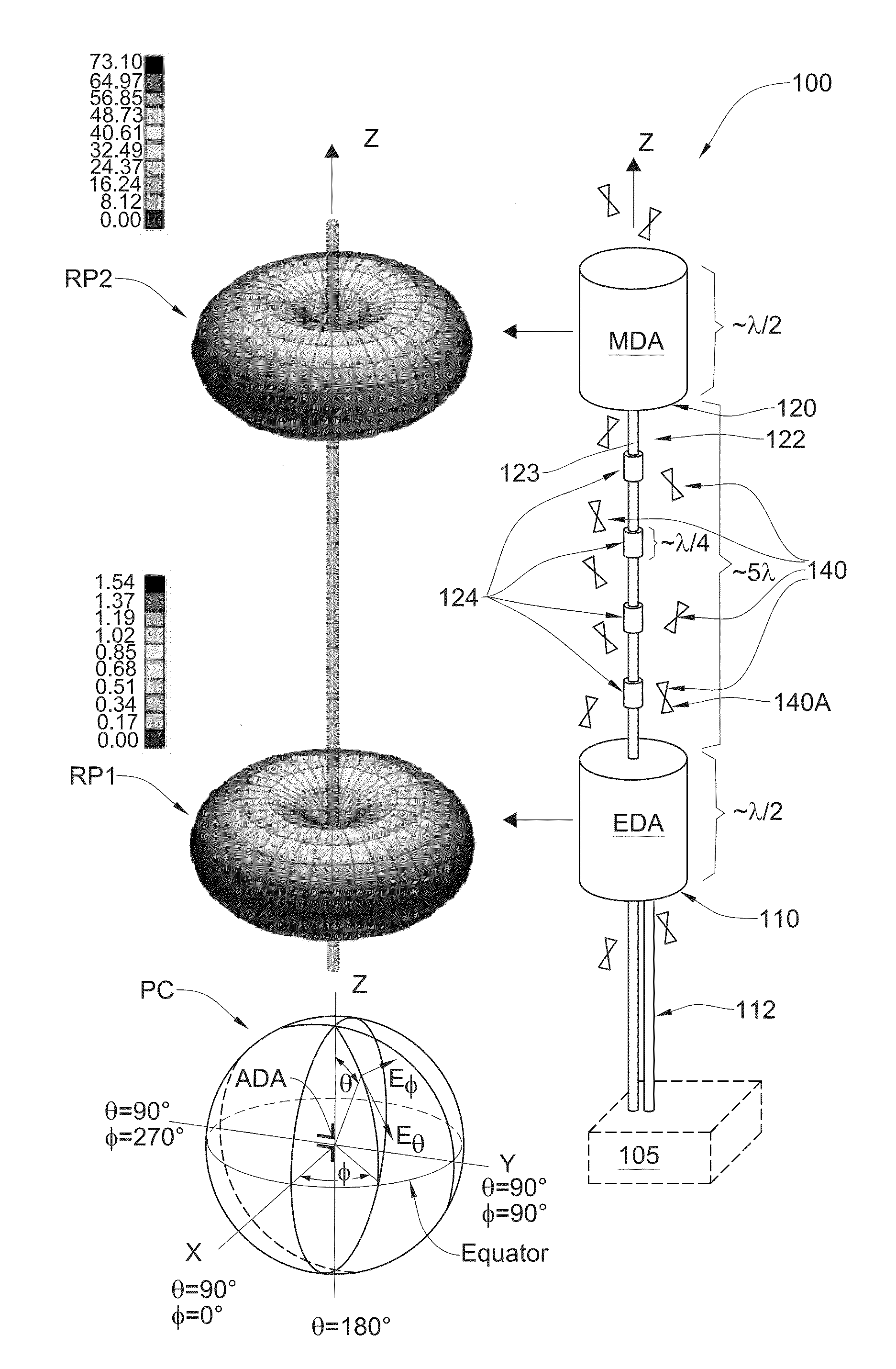
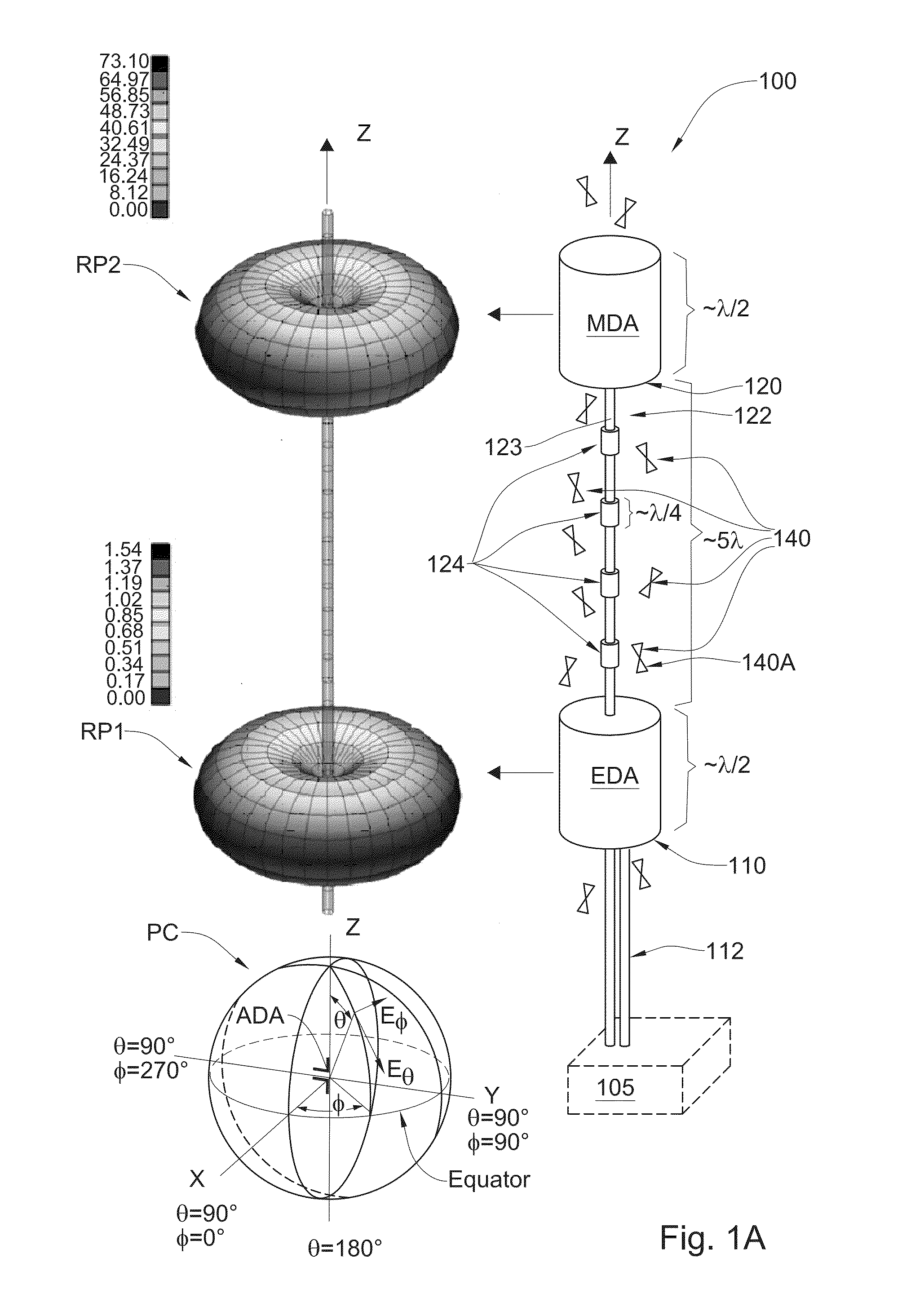
[0036]Reference is made to FIG. 1A showing a schematic illustration of an antenna system 100 according to an embodiment of the present invention. The antenna system 100 includes at least two antenna modules, 110 and 120, which are each configured and operable for transmitting and / or receiving of electromagnetic (EM) radiation. The operation of the antenna's for either one of reception or transmission, or for both reception and transmission, is generally referred to herein as transceiving operation. The two antenna modules 110 and 120 are configured and operable for transceiving EM radiation at a certain common wavelength band (common frequency band). In order to improve isolation of each of the antennas 110 and 120 from one another (e.g. to reduce crosstalk between the antennas at the common frequency band), the two antenna modules 110 and 120 are collinearly arranged along a common longitudinal axis Z with a certain minimal distance therebetween, which is of at least few nominal wa...


PUM


Abstract

The present invention relates to an antenna system including at least two antenna modules operable for transmitting and / or receiving radiation in certain common frequency band. The at least two antenna modules are collinearly arranged along a common axis so as to provide low gain along the axis, and are spaced apart from one another along this axis by a distance of at least a few nominal wavelengths of the common frequency band. Each two locally adjacent antenna modules of the at least two antenna modules operate with substantially mutually orthogonal polarizations of radiation, thereby suppressing electromagnetic coupling between the antenna modules in the common frequency band.

Description

FIELD AND BACKGROUND OF THE INVENTION[0001]This invention is generally in the field of antennas, and relates to a multiple antenna system configured for reducing cross talk between neighboring antennas.[0002]Various antenna systems utilize multiple antenna elements to transmit and / or receive electromagnetic signals simultaneously. In cases where the antenna elements are located in relative proximity, substantial coupling and crosstalk between the proximate antennas may introduce noise in the signals transmitted and / or received thereby. Conventional techniques, for reducing the isolation between the antennas include increasing a distance between the antennas and / or utilizing electromagnetic radiation shields between the antennas including for example absorbing materials and / or conductive plates. Such techniques are generally associated with large dimensions and / or weight of the system and / or with low isolation between the antennas which make them less suitable for certain application...

Claims


Application Information

Patent Timeline
Patent Type & Authority Applications(United States)
IPC IPC(8): H01Q1/52H01Q21/10H01Q21/28H01Q9/18
CPCH01Q21/10H01Q9/18H01Q21/28H01Q1/521H01Q21/24
Inventor ALMOG, BENYAMIN
Owner ELTA SYST LTD
Learn More