Vacuum gripper
a vacuum gripper and vacuum technology, applied in the direction of vacuum grippers, lighting and heating apparatuses, furnace components, etc., can solve the problems of workpiece overflow, workpiece overflow, and high cost of control of such highly dynamic processes
- Summary
- Abstract
- Description
- Claims
- Application Information
AI Technical Summary
Benefits of technology
Problems solved by technology
Method used
Image
Examples
Embodiment Construction
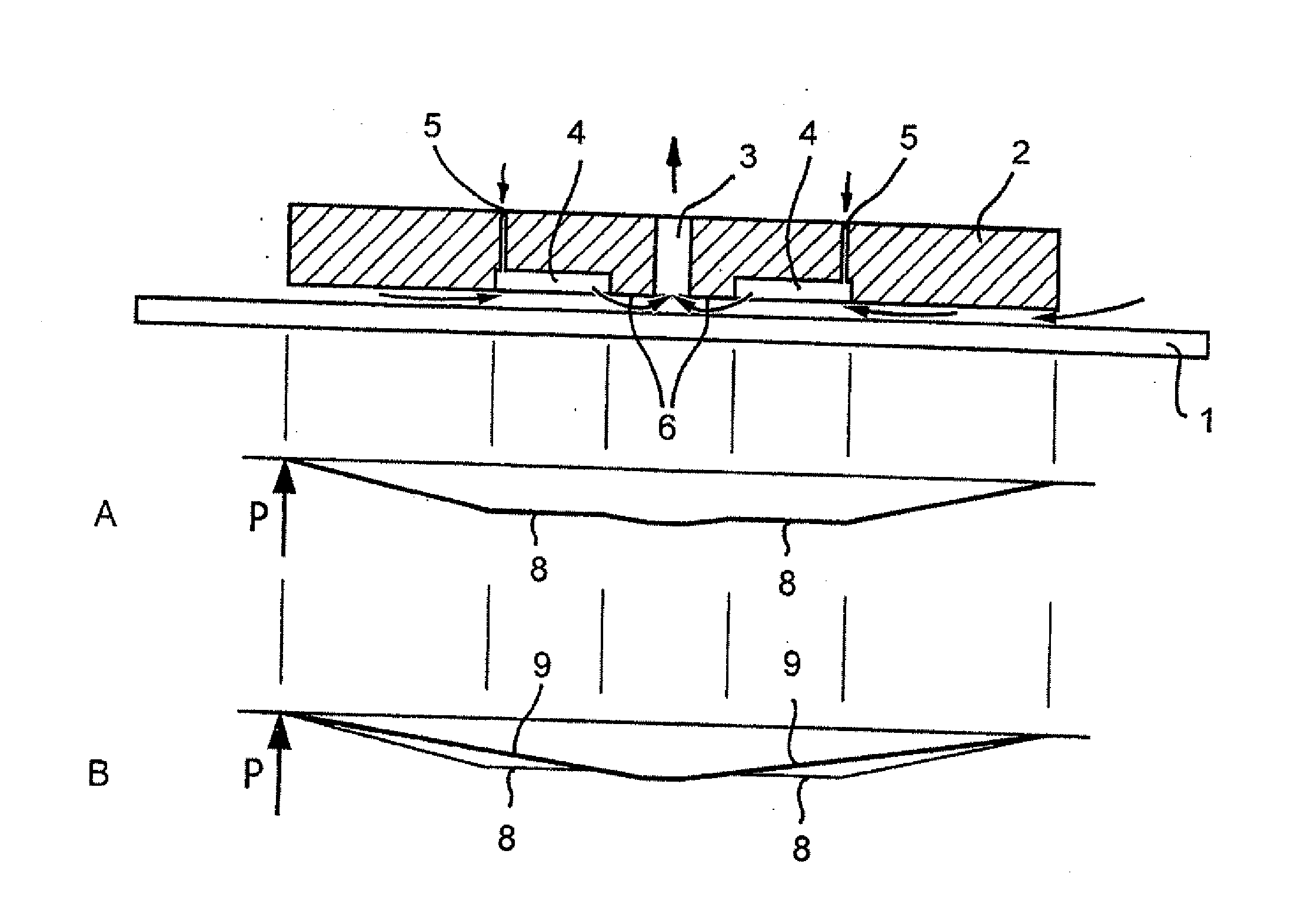
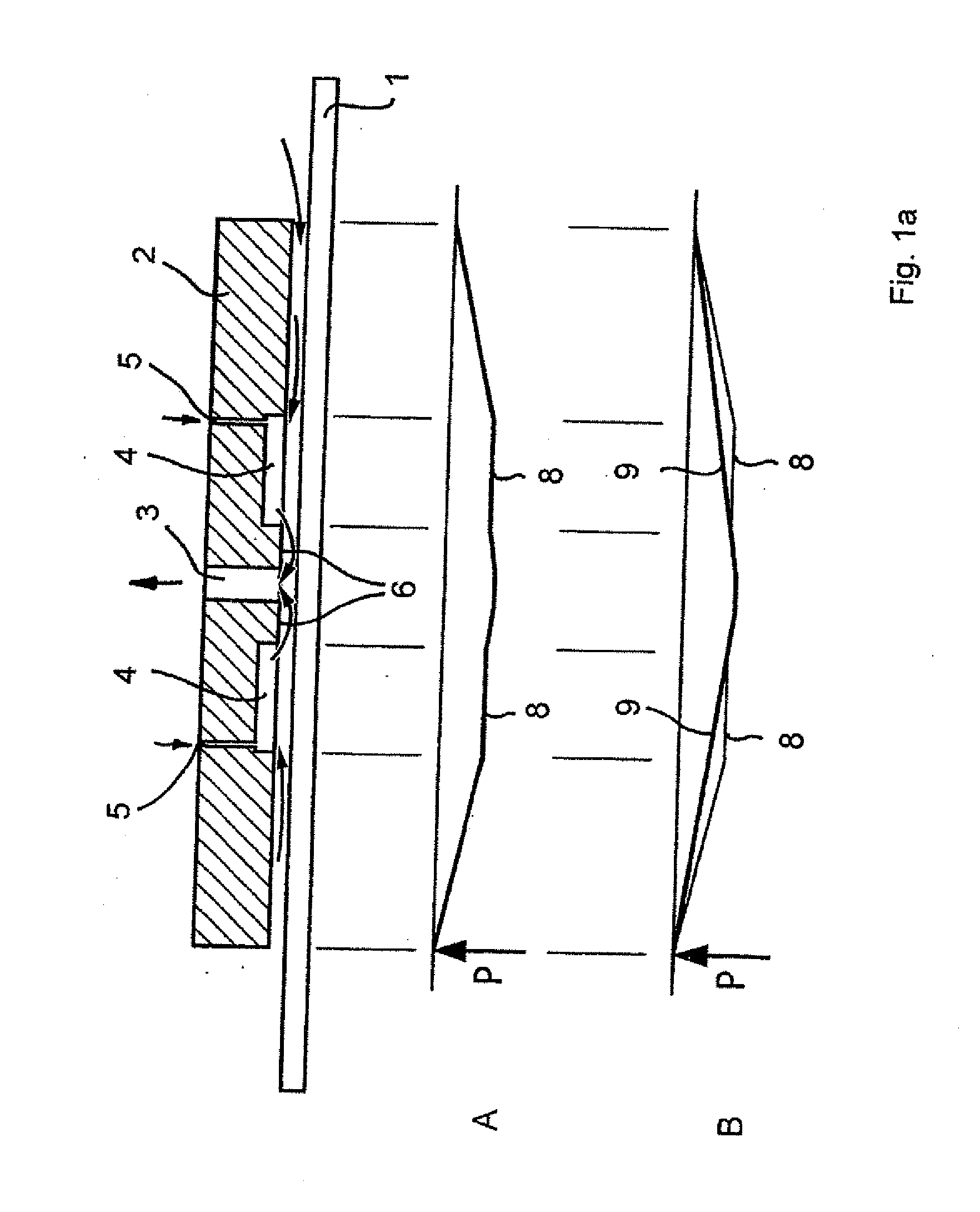
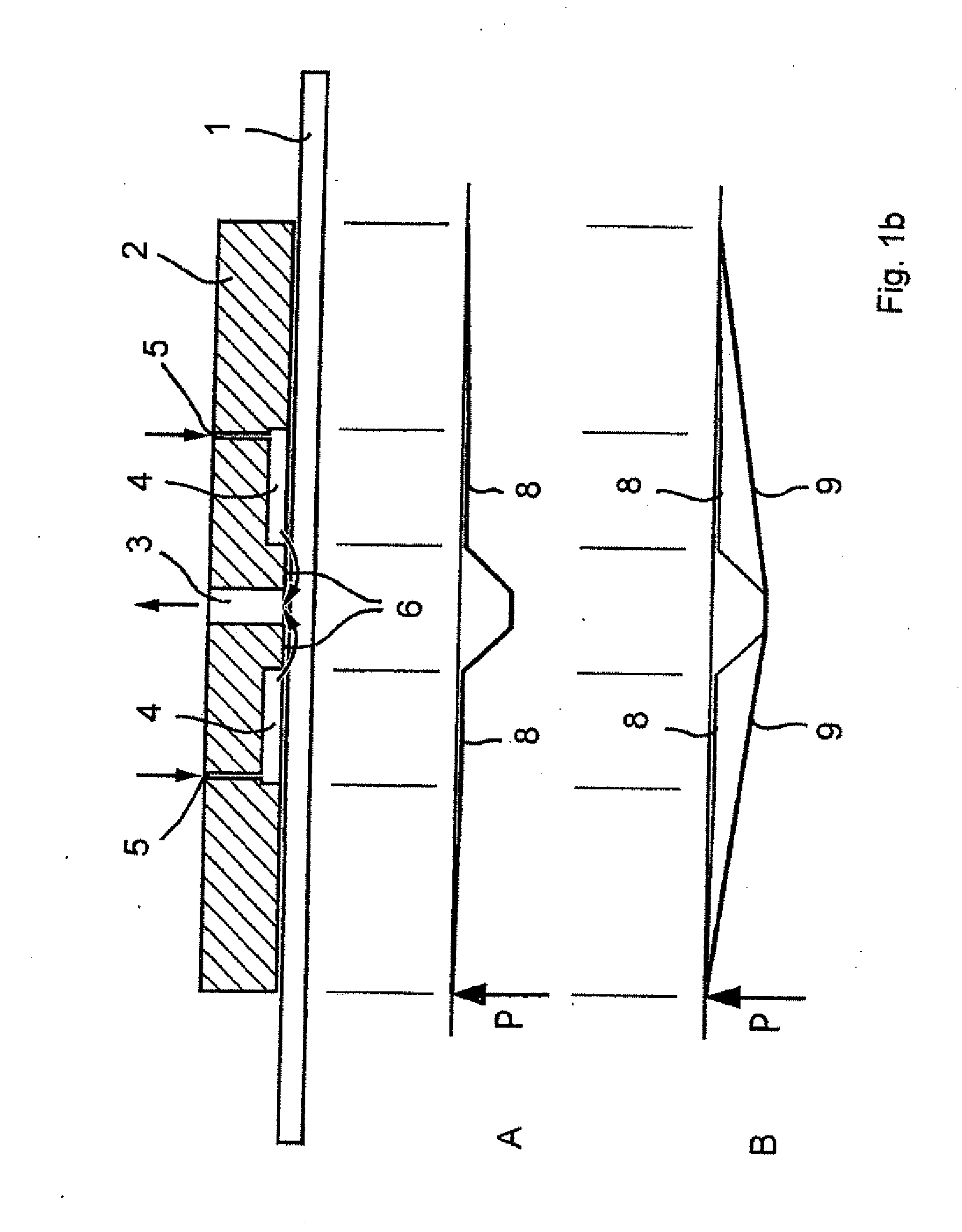
[0042]FIGS. 1a, b show a cross-sectional view of a circular vacuum gripper for carrying a work-piece 1, wherein the vacuum gripper comprises the following features: a disk-shaped round gripper plate 2 provided with a suction port 3 in its center. A round annular work-piece throttling zone 6 is formed around the suction port 3, the operating characteristics of which being explained in the consecutive section. The gripper plate 2 is also provided with an annular recess 4 extending towards the margin of plate, which has two vent holes 5 dislocated to each other by 180 degrees, that is, the entire recess 4 is connected with the atmosphere.
[0043]FIG. 1a shows the work-piece 1 still in its initial position. By the suction action of the gripper, air is sucked from the outside of gripper through the gap 7 usually having a width of about 2 mm to 0.8 mm and flows through the suction port 3. In this position, the vacuum gripper generates its maximum suction force being greater than the weight ...
PUM
 Abstract
Description
Claims
Application Information
 - R&D
- Intellectual Property
- Life Sciences
- Materials
- Tech Scout
- Unparalleled Data Quality
- Higher Quality Content
- 60% Fewer Hallucinations
Browse by: Latest US Patents, China's latest patents, Technical Efficacy Thesaurus, Application Domain, Technology Topic, Popular Technical Reports.
© 2025 PatSnap. All rights reserved.Legal|Privacy policy|Modern Slavery Act Transparency Statement|Sitemap|About US| Contact US: help@patsnap.com


