
Transformer Hydrogen Indicator

a transformer and hydrogen gas technology, applied in the direction of chemical indicators, instruments, food testing, etc., can solve the problems of transformer explosion, large amount of hydrogen gas generated by mineral transformer oils, and increased degradation rate, so as to achieve reliable and low cost

Active Publication Date: 2014-11-06
SERVERON CORP
View PDF6 Cites 1 Cited by
  • Summary
  • Abstract
  • Description
  • Claims
  • Application Information

AI Technical Summary

Benefits of technology

The present invention is a hydrogen indicator for use with transformers. It is a small, threadable module that contains a special film that changes color when exposed to hydrogen. The color change is visible through a lens, allowing quick visual inspection of the module to determine if hydrogen has been generated in the transformer. The hydrogen indicator is reliable and low-cost, providing a safe way to detect the presence of dangerous levels of hydrogen gas.

Problems solved by technology

These conditions can cause mineral transformer oils to decompose generating relatively large quantities of hydrogen gas, which is highly volatile, and which in some instances may accumulate in a transformer under relatively high pressure.
Left undetected or uncorrected, equipment faults can lead to an increased rate of degradation, and even to catastrophic explosion of the transformer.
Transformer failure is a significantly expensive event for an electric utility, not only in terms of down time and the costs of replacement equipment, but also in terms of the costs associated with lost power transmission.
Despite the known need for reliable equipment to monitor gas in oil, designing equipment that holds up to the rigors of on-site conditions has been problematic for a variety of reasons.
Although these devices have provided benefits, they have significant limitations when used to monitor smaller transformers used in connection with, for example, pole-mounted distribution transformers used by electric utilities.
Not only are these types of transformers too difficult to access for routine monitoring, but the costs and difficulties associated with either extracting gas from or installing extractors into such small devices makes the foregoing types of monitoring unpractical.
Moreover, there are numerous practical problems remaining to the development of reliable apparatus for extraction, monitoring and analysis of fault gases in transformer oils.
Many of these problems relate to the design of reliable fluid routing systems that are redundant enough to provide a relatively maintenance free unit.
Since transformers are often located in exceedingly harsh environmental conditions, fluid routing problems are magnified.
This is especially true given that the instruments needed to reliably analyze the gases are complex analytical instruments.
However, such devices tend to be very expensive and are therefore limited to larger electrical assets—the costs of the equipment and the monitoring programs that go with them are too high to justify using the devices with relatively smaller assets such as transformers used by utilities for routine power delivery systems.
But the problems with fault gas accumulation in transformers are not limited to the large systems that can be monitored with existing systems such as those described above and the expenses that are caused by transformer failure are a significant part of many utilities' business.

Method used


Image

  • Transformer Hydrogen Indicator
  • Transformer Hydrogen Indicator
  • Transformer Hydrogen Indicator

Examples


Embodiment Construction

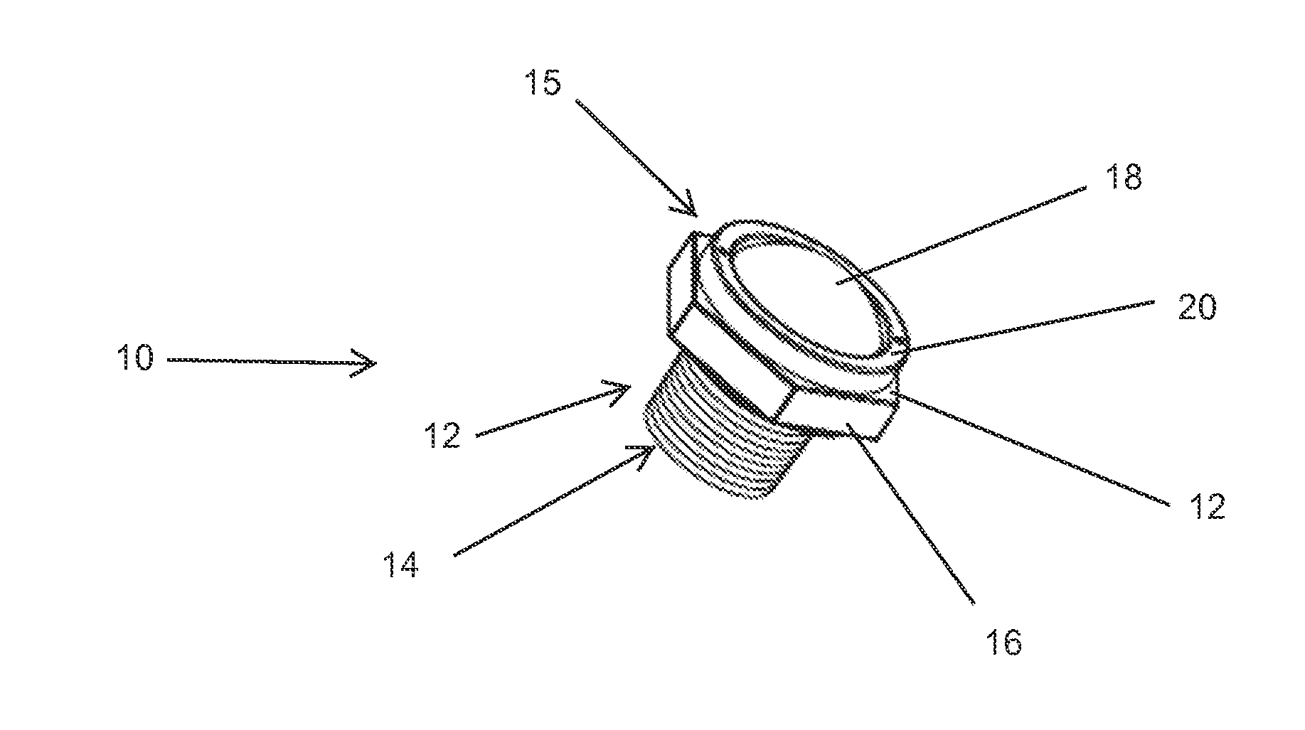
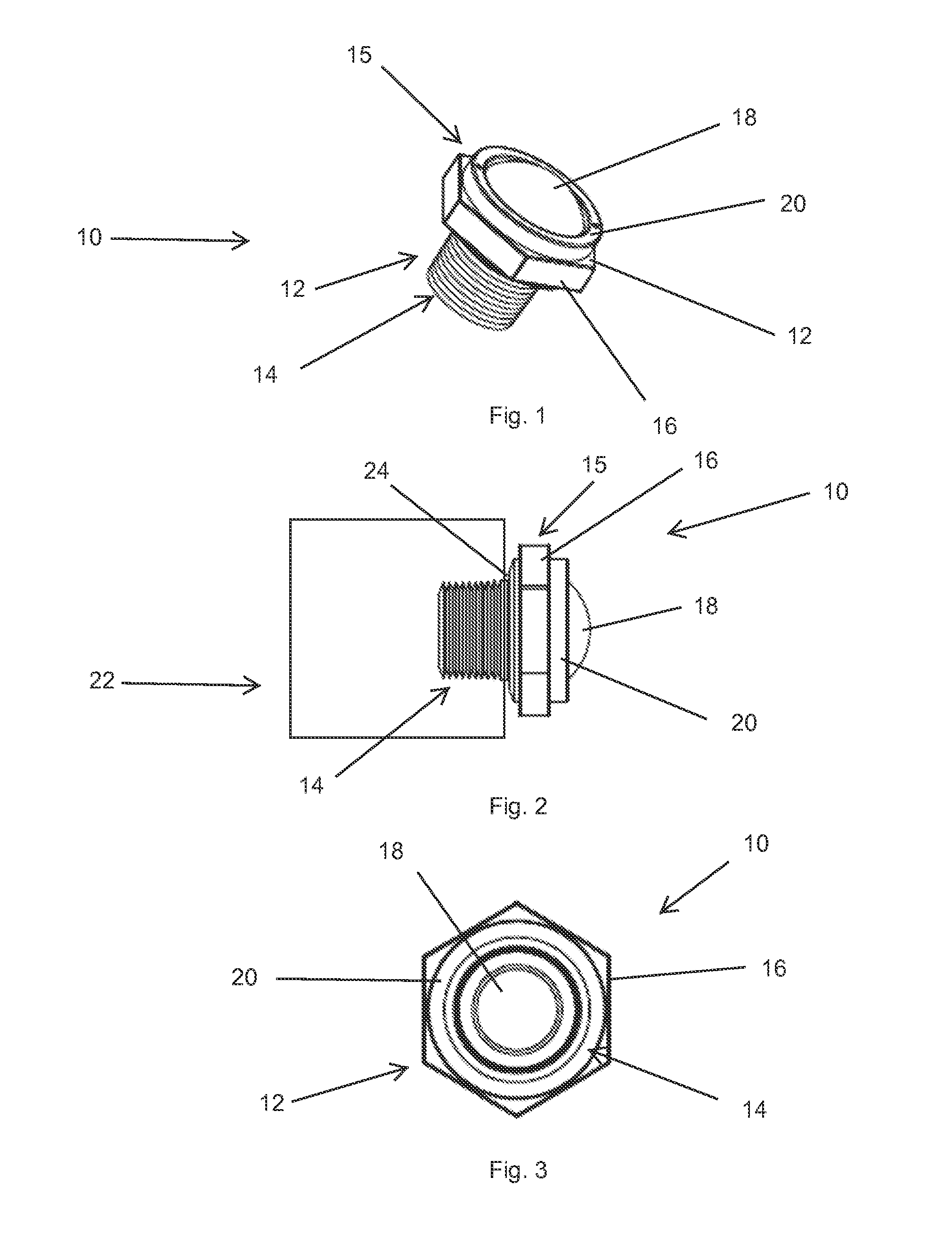
[0018]With reference to FIGS. 1 through 3, a transformer hydrogen indicator module 10 according to the present invention is shown in an assembled state. The module 10 comprises a body 12 having a threaded end 14 that is in use threaded into a threaded opening in a transformer, and an exposed end 15 that preferably is defined in part by a hexagonal head 16 and which in use is located externally of the transformer. A translucent lens 18 is found on the exposed end and is held in place in the assembled module with a collar clamp ring 20.

[0019]A transformer 22 is shown schematically in FIG. 2 with module 10 threaded into a threaded port 24 in the transformer—the port 24 opens to the interior of the transformer where the insulating oil is contained. The port 24 may be positioned either above or below the level of insulating oil contained in the transformer. That is, the module 10 may be located in the transformer such that the module is in the headspace above the oil, or such that the mo...


PUM

PropertyMeasurementUnit
gas permeableaaaaaaaaaa
color changeaaaaaaaaaa
pressureaaaaaaaaaa

Abstract

A reliable, low cost device for determining when dangerous levels of hydrogen gas have been generated in a transformer is disclosed. The hydrogen indicator is defined by a module assembly that threads into either the headspace or into the oil-filled body of a transformer. The module has an open interior that contains a film that incorporates a hydrogen-sensitive chemochromic indicator. The indicator film is visible through a lens. When the film has been exposed to hydrogen, chemical changes in the chemochromic indicator cause the film to change color—the color change is immediately visible through the lens.

Description

FIELD OF THE INVENTION[0001]The present invention relates to apparatus and methods for detecting the presence of hydrogen in electrical transformers, and more particularly, a module assembly that may be attached to existing or new transformers and which includes a chemochromic indicator that changes color in the presence of hydrogen.BACKGROUND OF THE INVENTION[0002]The electric power industry has for many years recognized that thermal decomposition of the oil and other insulating materials within oil-insulated electrical apparatus can lead to the generation of a number of “fault gases.” These phenomena occur in equipment such as oil filled transformers (both conservator and gas-blanketed types), load tap changers, transformer windings, bushings and the like. The detection of specific fault gases in electrical apparatus can be an important part of a preventative maintenance program.[0003]The presence of fault gases in oil-blanketed transformers with conservators and other utility ass...

Claims


Application Information

Patent Timeline
Patent Type & Authority Applications(United States)
IPC IPC(8): G01N33/28
CPCG01N33/2841Y10T436/22Y10T436/25875
Inventor MAHONEY, STEVEN
Owner SERVERON CORP
Learn More