
Apparatus for storing a plurality of objects such as trays

a technology for storing objects and trays, which is applied in the direction of movable shelf cabinets, variable height tables, dismountable cabinets, etc., can solve the problems of cumbersome limited space, possible health and safety issues, and work height, so as to facilitate the movement of the platform, facilitate the storage of multiple units, and improve access

Inactive Publication Date: 2015-01-15
LINNELL MICHAEL CHARLES SR +3
View PDF87 Cites 9 Cited by
  • Summary
  • Abstract
  • Description
  • Claims
  • Application Information

AI Technical Summary

Benefits of technology

The present invention provides an apparatus for loading objects at different heights. The apparatus includes a platform that can move between two positions. This reduces the difficulty of loading objects at different heights. The platform can be moved along a post located outside its footprint, allowing other objects to be stored underneath it. The apparatus also includes a body with moveable side members that can be nested when not in use for easy storage. The platform can be supported by the side members when moving between its operative and inoperative positions. The apparatus also includes an expandable container for storing objects, which can be secured to the platform and expanded as it moves. The technical effects of this invention include improved efficiency and ease of use for loading objects at different heights.

Problems solved by technology

Such variations in working height are considered at the very least an inconvenience, and possibly even a health and safety issue.
Furthermore, once the top trays have been unloaded and emptied, they must be put to one side because they cannot be placed back on the trolley until the last tray has been unloaded.
Thus, unloading the trolley in a limited space can be cumbersome and waiting until the last tray is unloaded before placing the empty trays on the trolley may add to the time it takes to return the trolley for re-use.

Method used


Image

  • Apparatus for storing a plurality of objects such as trays
  • Apparatus for storing a plurality of objects such as trays
  • Apparatus for storing a plurality of objects such as trays

Examples


Embodiment Construction

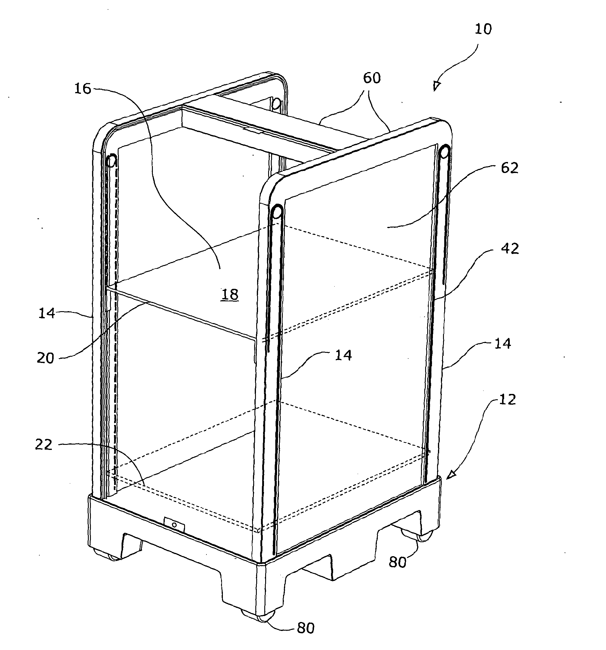
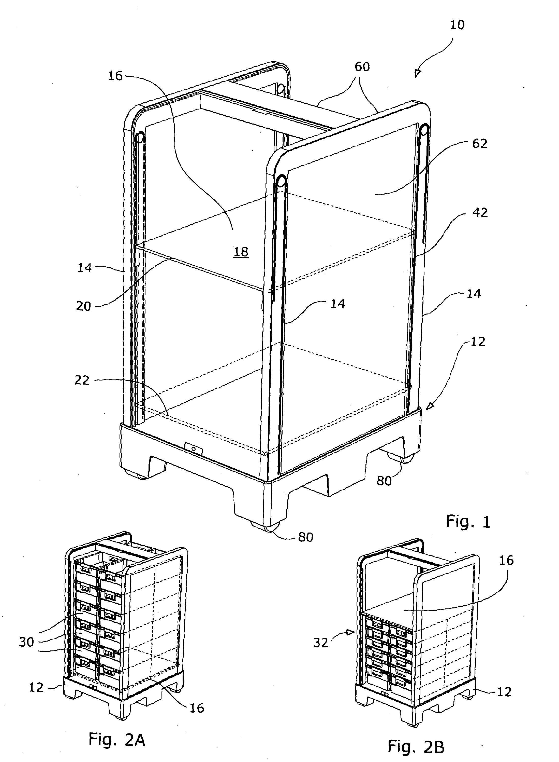
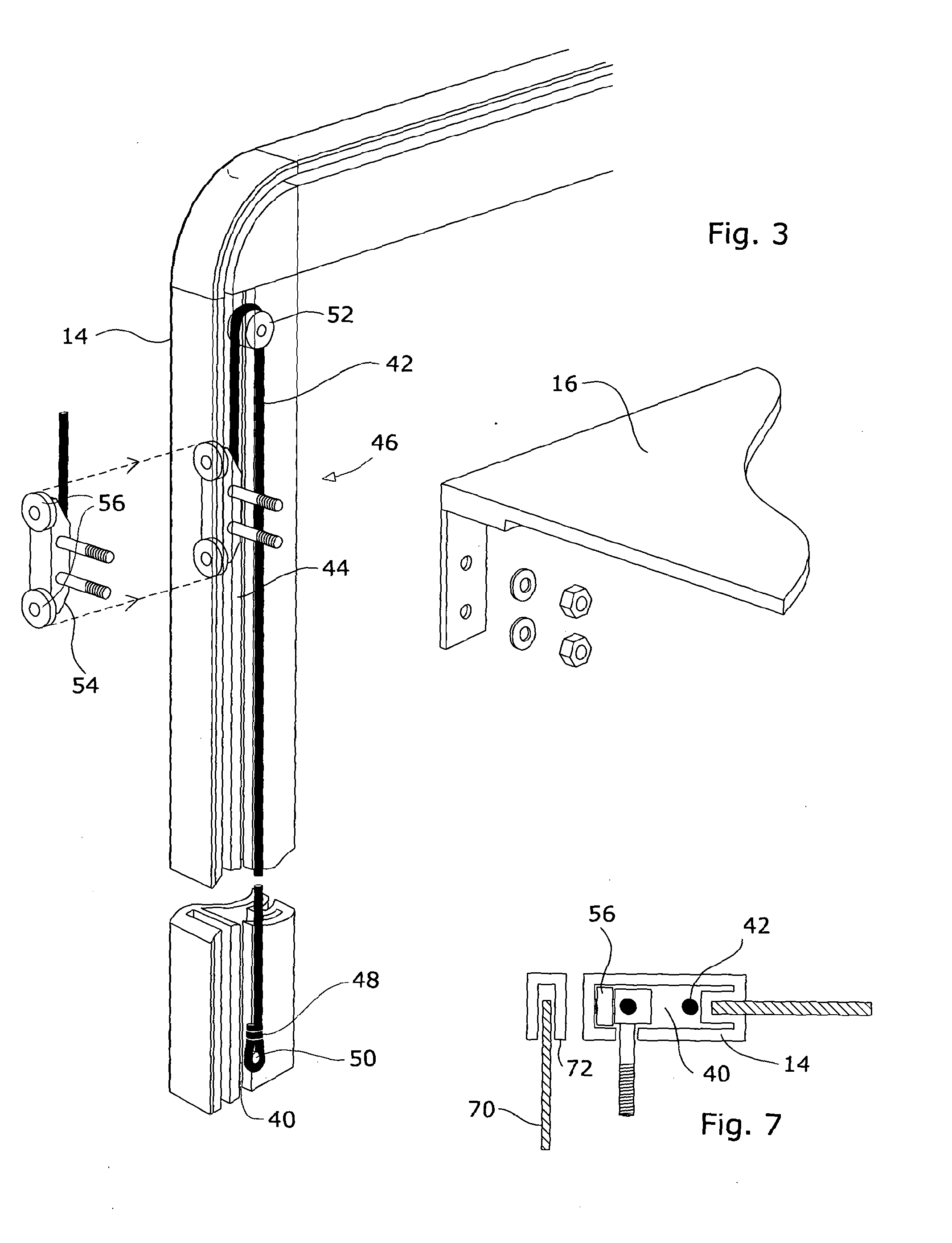
[0031]FIG. 1 illustrates apparatus 10 in accordance with one embodiment of the present invention, and comprising a base 12, a plurality of posts 14 attached to the base 12, and a platform 16 defining a surface 18 for supporting at least one mail tray. The platform 16 is coupled to the four posts 14 and is moveable therealong between a first position 20 and a second position 22 (shown in phantom lines) below the first position 20 when a first object (e.g. a full tray 30) is supported on the surface 18 of the platform 16. As more full trays 30 are stacked on the apparatus 10, the platform 16 is displaced further from the first position 20 until eventually it reaches the base 12, as shown in FIG. 2A. As the full trays 30 are unloaded from the apparatus 10, the platform 16 rises upwards until it returns to the first position 20 when none remain on the surface 18. As the platform 16 rises, a space 32 between the platform 16 and the base 12 opens up and is a convenient place to store empt...


PUM


Abstract

Apparatus (10) comprises a base (12), a plurality of posts (14) attached to the base (12), and a platform (16) defining a surface (18) for supporting at least one mail tray. The platform (16) is coupled to the four posts (14) and is moveable therealong between a first position (20) and a second position (22) (shown in phantom lines) below the first position (20) when a first object (e.g. a full tray) is supported on the surface (18) of the platform (16). As other full trays are stacked on the apparatus (10), the platform (16) is displaced further from the first position (20) until eventually it reaches the base (12). When the full trays are unloaded from the apparatus (10), the platform (16) rises upwards, returning to the first position (20) when none remain on the surface (18). As the platform (16) rises, a space (32) between the platform (16) and the base (12) opens up and is a convenient place to store empty trays.

Description

TECHNICAL FIELD[0001]The invention relates to apparatus for storing a plurality of objects such as trays, and more particularly, but not exclusively, to a trolley including such apparatus for temporarily storing mail received in the plurality of trays.BACKGROUND ART[0002]It is known to provide a trolley for transferring mail from one location (e.g. source) to another location where it is to be sorted. If the mail is received in trays, the trays will typically be stacked one on top of the other, meaning that the height at which a tray must be loaded on to the trolley depends upon the number of trays already stacked on it. Similarly, the height at which a tray must be unloaded from the trolley will depend upon the number of trays stacked beneath it. Such variations in working height are considered at the very least an inconvenience, and possibly even a health and safety issue. Furthermore, once the top trays have been unloaded and emptied, they must be put to one side because they can...

Claims


Application Information

Patent Timeline
IPC IPC(8): B62B3/00B65D19/42B65D33/00B65D19/02A47B57/10B62B5/04B62B3/02
CPCA47B57/10B62B3/005B65D19/02B65D19/42B62B5/04B65D33/00B62B3/006B62B3/02B07C7/02B62B3/16B62B3/186B62B5/0013B62B3/025B65D21/0204B62B2202/64B62B2203/13B62B2205/33B65D2519/00805B65D2519/00781B65D2519/0082B65D2519/0097B62B2207/02B62B3/18
Inventor LINNELL, SR., MICHAEL CHARLESLINNELL, JR., MICHAEL CHARLES
Owner LINNELL MICHAEL CHARLES SR
Learn More