
Oil pump

Inactive Publication Date: 2015-01-08
MIKUNI CORP
View PDF10 Cites 1 Cited by
  • Summary
  • Abstract
  • Description
  • Claims
  • Application Information

AI Technical Summary

Benefits of technology

The present invention provides an oil pump that can maintain good performance even when sucking oil through a purge port. The pump includes a housing with an inlet, outlet, and purge port, an inner rotor, and an outer rotor. A filter member is also included to prevent foreign matter from entering through the purge port. The oil pump can improve performance and durability in a wide engine revolution range, including a range with less air mixing.

Problems solved by technology

On the other hand, owing to a high oil level in the oil pan at engine starting or following delay of an intake process at high speed revolution, there maybe a case that oil is sucked through the purge port.

Method used


Image

  • Oil pump
  • Oil pump
  • Oil pump

Examples


Embodiment Construction

[0040]In the following, embodiments of the present invention will be described with reference to the attached drawings.

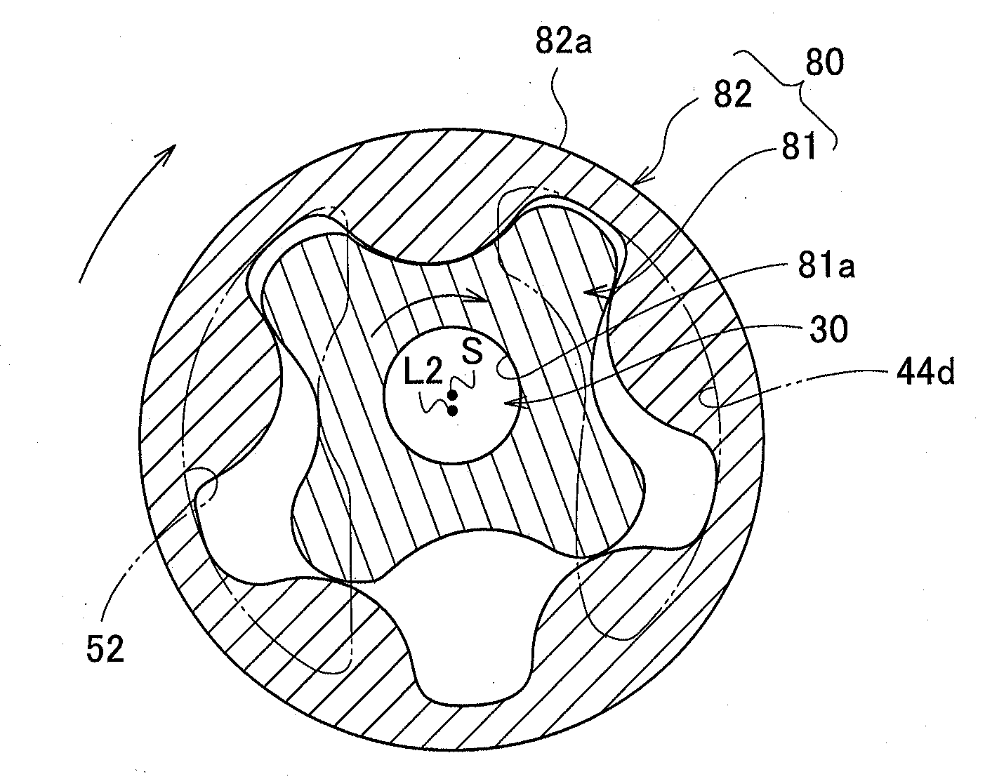
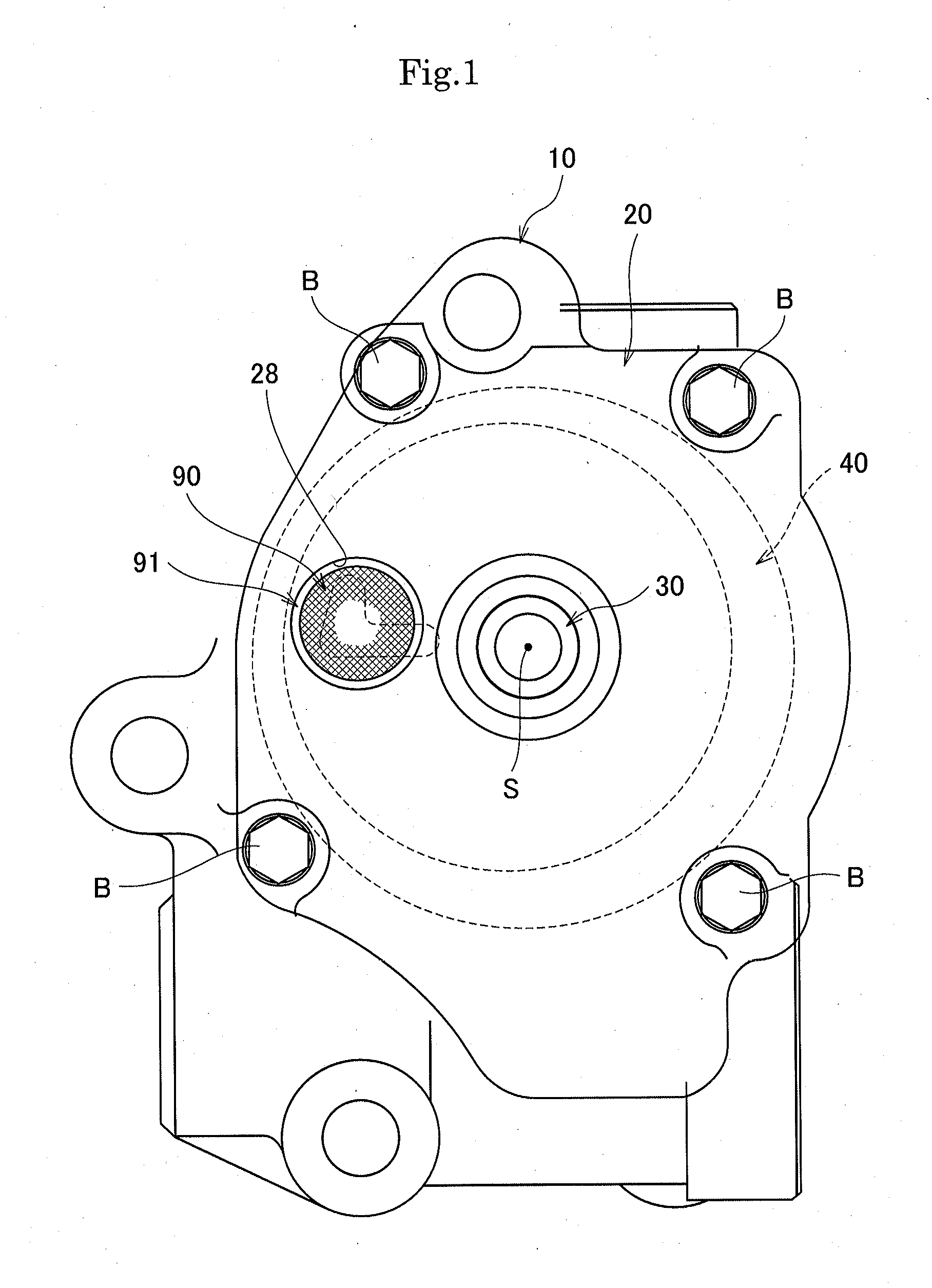
[0041]As illustrated in FIGS. 1 and 2, an oil pump according to an embodiment includes a housing body 10 and a housing cover 20 which constitute a housing, a rotary shaft 30 which is supported by the housing as being rotatable about an axis line S, a rotor case 40 which is assembled in the housing, a side plate 50 which is in contact with an end face of the rotor case 40, an O-ring 60 as an urging member which urges the side plate 50 toward the rotor case 40 in the direction of the axis line S, an upstream rotor 70, including a first inner rotor 71 and a first outer rotor 72, which is contained in the rotor case 40, a downstream rotor 80, including a second inner rotor 81 and a second outer rotor 82, which is contained in the rotor case 40 as being adjacent to the upstream rotor 70 in the direction of the axis line S, a filter member 90 which is attached to the hous...


PUM


Abstract

An oil pump of the present invention includes a housing (10, 20) which includes an inlet port (44b) to suck oil, a discharge port (52) to discharge oil, and a purge port (24) to eject air-mixed oil, an inner rotor (71, 81) which is arranged in the housing as being rotatable about a predetermined axis line (S), an outer rotor (72, 82) which is arranged in the housing to be rotated as being interlocked with the inner rotor, and a filter member (90) which is arranged at the housing from the outside thereof to prevent foreign matter from entering through the purge port. According to the above, entering of foreign matter and the like can be prevented even when oil is sucked through the purge port.

Description

TECHNICAL FIELD[0001]The present invention relates to an oil pump which sucks and discharges oil (lubricant oil) of an internal combustion engine (an engine) or the like, and in particular, relates to a trochoid type oil pump including an inner rotor and an outer rotor.BACKGROUND ART[0002]There has been known a trochoid type oil pump including a housing which has an inlet port for sucking oil, a discharge port for discharging oil, a purge port (an air vent port, a bubble ejection port, or a deairing port) for ejecting air mixed with oil, and the like, an outer rotor which has internal teeth as being rotatably arranged in the housing, an inner rotor which has external teeth engaged with the internal teeth of the outer rotor and which defines a volume-varying pump chamber in cooperation with the outer rotor, a rotary shaft which is rotatably supported by the housing to rotate the inner rotor, and the like. Here, pumping action is obtained by rotating the inner rotor via the rotary sha...

Claims


Application Information

Patent Timeline
IPC IPC(8): F04C15/06F04C2/10
CPCF04C2/102F04C15/064F04C2280/02F04C14/28F04C2220/20
Inventor ODA, HIROYUKI
Owner MIKUNI CORP
Learn More