
Phosphor wheel heat-dissipating module for laser projection system

a technology of laser projection system and heat dissipation module, which is applied in the direction of lighting and heating apparatus, instruments, optics, etc., can solve the problems of difficult to maintain the balance easy burnout of the phosphor agent, and gradual increase of the required energy of the laser light source, so as to achieve effective heat removal without increasing the area of the phosphor wheel

Active Publication Date: 2015-01-08
DELTA ELECTRONICS INC
View PDF1 Cites 38 Cited by
  • Summary
  • Abstract
  • Description
  • Claims
  • Application Information

AI Technical Summary

Benefits of technology

The present invention is a phosphor wheel heat-dissipating module for a laser projection system. The module improves heat removal without increasing the size of the phosphor wheel. The result is higher heat-dissipating efficiency, reducing local temperature differences and improving overall system performance. This allows the phosphor wheel to handle higher energy laser beams without increasing its size.

Problems solved by technology

), and the phosphor agent is readily burnt out.
However, with the increasing demands on the luminance of optical products, the required energy of the laser light sources are gradually increased.
However, the increased area of the phosphor wheel may bring some problems.
Since the area of the phosphor wheel is increased, it is difficult to maintain the balance of the phosphor wheel.
As known, there are few commercially-available motors that match the large-sized phosphor wheel.
Moreover, as the speed of the motor is increased, the problem of causing noise is increased.
Due to the limitations of the size of the phosphor wheel and the corresponding requirement of the motor, the high energy laser light source is not suitably used in the conventional laser projection system.
In other words, if the area of the phosphor wheel and the rotating speed of the motor fail to be increased, the luminance of the laser projection system is restricted.
Moreover, even if the rotating speed of the motor for rotating the phosphor wheel is increased, since the phosphor wheel has a circular disc profile, another problem occurs.
For example, it is difficult to cause a pressure difference of the ambient air during rotation of the phosphor wheel.
Since the airflow cannot be effectively driven, the heat-dissipating efficacy is usually unsatisfied.

Method used


Image

  • Phosphor wheel heat-dissipating module for laser projection system
  • Phosphor wheel heat-dissipating module for laser projection system
  • Phosphor wheel heat-dissipating module for laser projection system

Examples


Embodiment Construction

[0015]The present invention will now be described more specifically with reference to the following embodiments. It is to be noted that the following descriptions of preferred embodiments of this invention are presented herein for purpose of illustration and description only. It is not intended to be exhaustive or to be limited to the precise form disclosed.

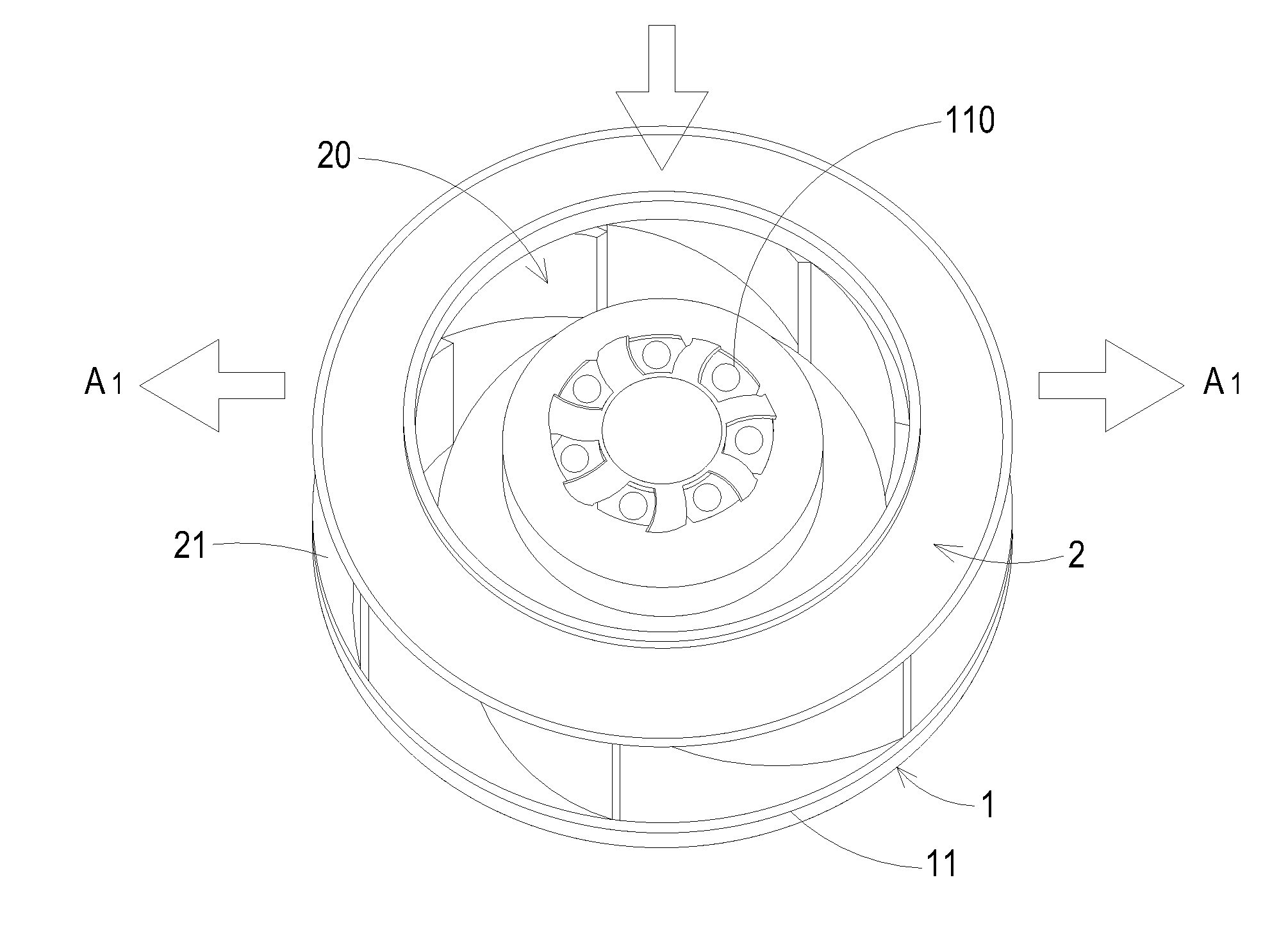
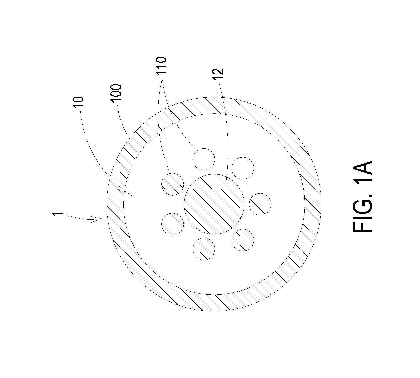
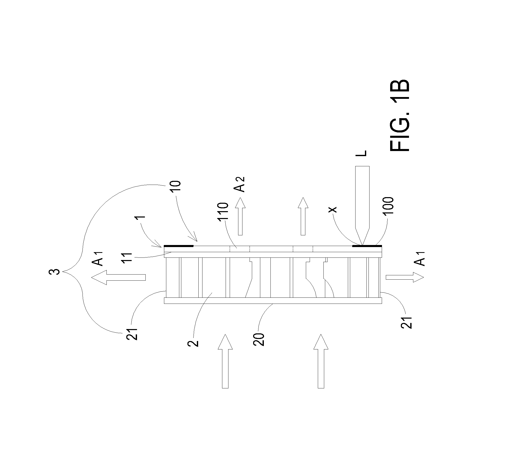
[0016]FIG. 1A is a schematic side view illustrating a first surface of a phosphor wheel of a phosphor wheel heat-dissipating module according to a first embodiment of the present invention. FIG. 1B is a schematic side view illustrating the phosphor wheel heat-dissipating module according to the first embodiment of the present invention. Please refer to FIGS. 1A and 1B. The phosphor wheel heat-dissipating module 3 is used in a laser projection system (not shown). The phosphor wheel heat-dissipating module 3 comprises a phosphor wheel 1, a plurality of air vents 110 and an impeller 2. In this embodiment, the phosphor wheel 1 has a ...


PUM


Abstract

A phosphor wheel heat-dissipating module for a laser projection system is provided. The phosphor wheel heat-dissipating module includes a phosphor wheel, a plurality of air vents and an impeller. At least one phosphor agent is coated on an outer-ring portion of a first surface of the phosphor wheel. The air vents run through the phosphor wheel. The impeller is disposed on a second surface of the phosphor wheel, and includes an inlet and a first outlet. A laser beam is projected on the outer-ring portion of the phosphor wheel. When the phosphor wheel is rotated at a high rotating speed, an airflow is inhaled into the impeller through the inlet. A first portion of the airflow is blown out through the first outlet, and a second portion of the airflow is transferred to the first surface of the phosphor wheel through the air vents.

Description

FIELD OF THE INVENTION[0001]The present invention relates to a heat-dissipating module, and more particularly to a phosphor wheel heat-dissipating module for effectively reducing the temperature of a phosphor wheel of a laser projection system.BACKGROUND OF THE INVENTION[0002]In the current laser projection system, a laser light source is used to emit a laser beam to excite a phosphor agent in order to generate color lights with different wavelengths. Since the laser beam has high energy and high collimation, the temperature of the laser beam is extremely high (e.g. the temperature may be close to or higher than 1000° C.), and the phosphor agent is readily burnt out. Nowadays, the phosphor agent is coated on an outer-ring portion of a phosphor wheel (also referred as color wheel), and the phosphor wheel is driven by a motor to be rotated at a high speed. Consequently, the energy absorbed by the phosphor agent per unit time is reduced, and the heat-dissipating efficacy is achieved. H...

Claims


Application Information

Patent Timeline
Patent Type & Authority Applications(United States)
IPC IPC(8): F21V9/08G03B21/16
CPCG03B21/16F21V9/08G03B21/204
Inventor WANG, HUI-HSIUNGSHA, YU-HSUAN
Owner DELTA ELECTRONICS INC
Learn More