Ventilator system

a ventilation system and ventilation valve technology, applied in the direction of valve operating means/release devices, machines/engines, liquid fuel engines, etc., can solve the problems of disrupting patient's rest, loud blower, and noise level in the patient's room

Inactive Publication Date: 2015-01-08
VYAIRE MEDICAL CAPITAL LLC
View PDF6 Cites 12 Cited by
  • Summary
  • Abstract
  • Description
  • Claims
  • Application Information

AI Technical Summary

Benefits of technology

[0016]Described herein are ventilators having a valve that is a software-controlled valve used to adjust the flow of gas passing through a port of the ventilator. The valve is controlled by a software control signal and works in conjunction with a ventilator's gas delivery subsystems to maintain user set pressure control levels. In continuous positive airway pressure (“CPAP”) therapy, the valve preferably helps maintain a set pressure.
[0027]It is advantageous to provide a modular flow cassette that provides accurate flow measurements of a variety of gases and gas mixtures over a range of temperatures and flow rates.

Problems solved by technology

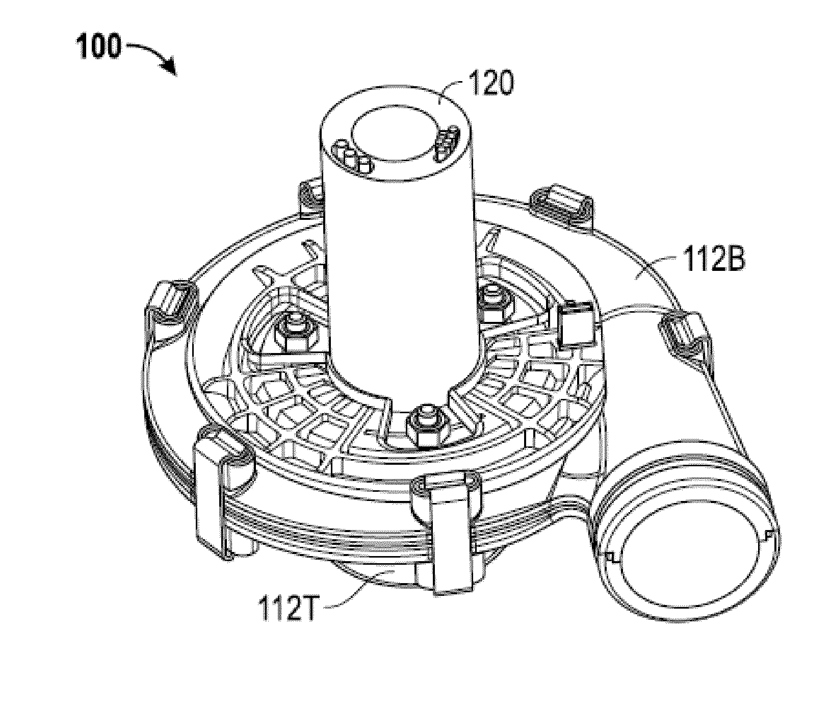
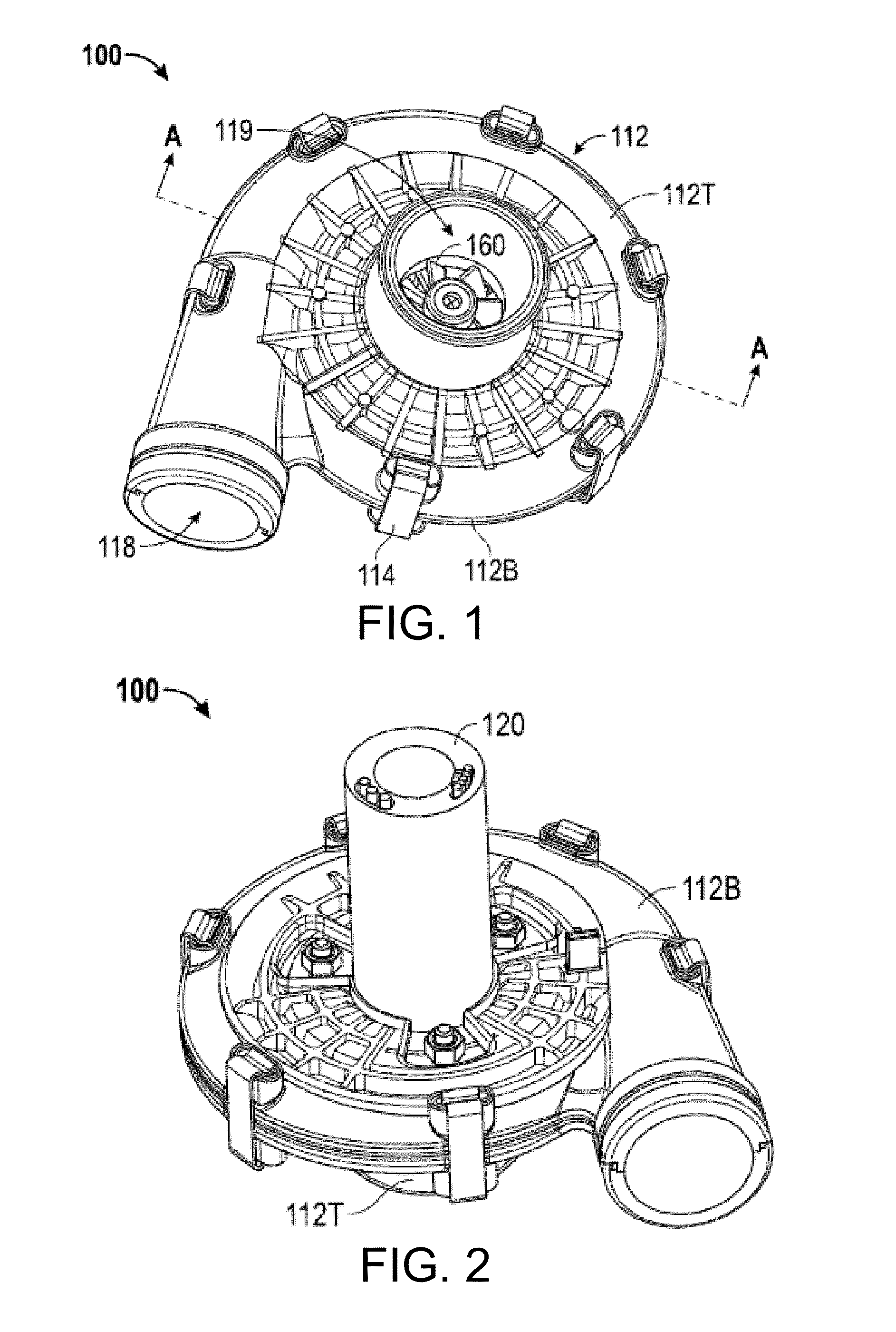
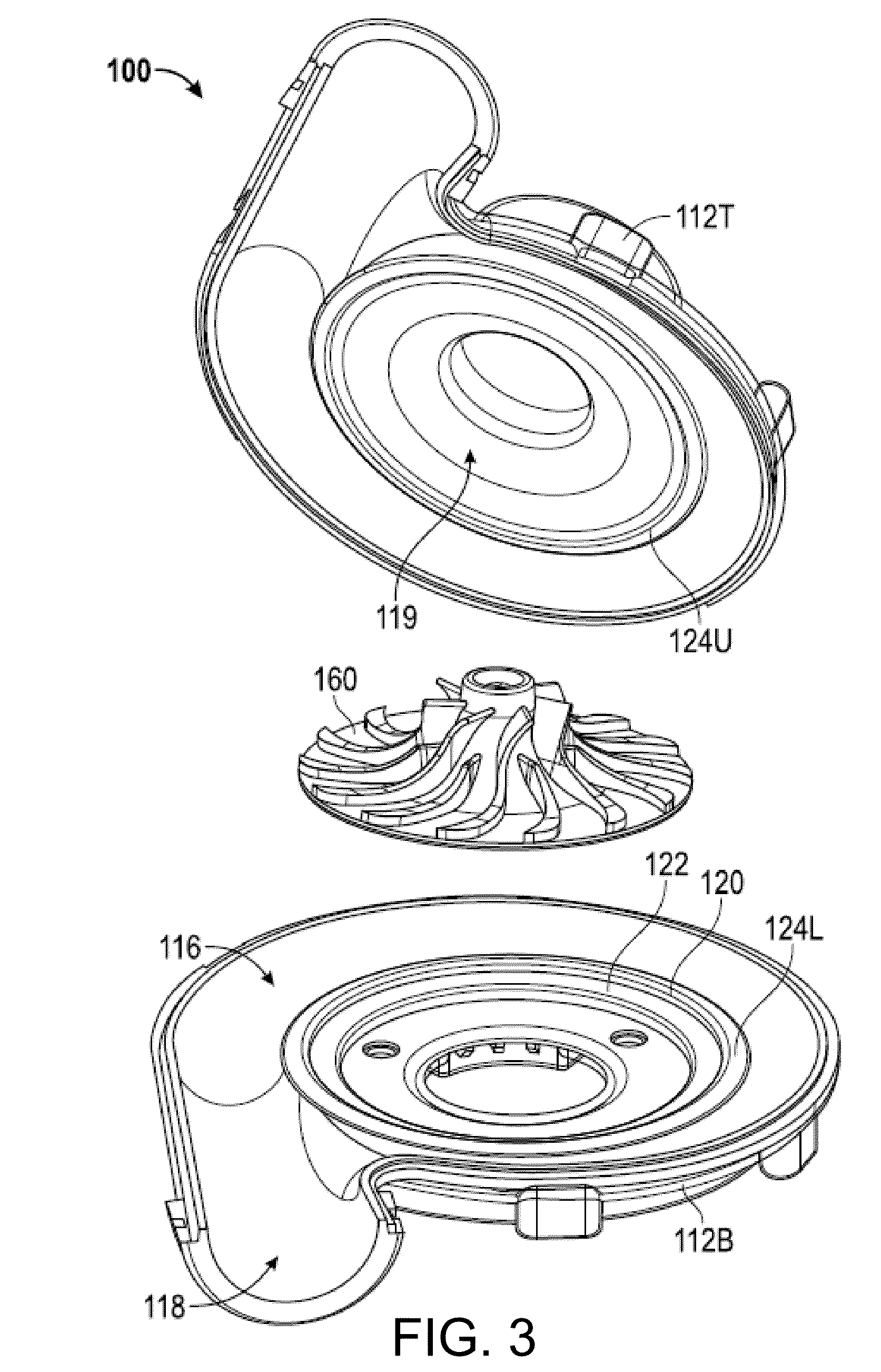
In some respirators that use a blower to pressurize the gas provided to the patient, the blowers that are used are loud and the noise level in the patient's room is commonly 65 dB or more.
This level of noise may disrupt the patient's rest and sleep as well as cause fatigue for the caregiver and may further obstruct diagnosis and monitoring of the patient by masking the natural breathing noises that provide an indication of the patient's condition.
The exact gas mixture delivered to the patient, however, may be a mixture of various breathing gases since the specific percentage required for a particular patient may not be commercially available and must be custom mixed in the respirator.

Method used


Image

  • Ventilator system
  • Ventilator system
  • Ventilator system

Examples


Embodiment Construction

[0071]In the following detailed description, numerous specific details are set forth to provide a full understanding of the present disclosure. It will be apparent, however, to one ordinarily skilled in the art that embodiments of the present disclosure may be practiced without some of the specific details. In other instances, well-known structures and techniques have not been shown in detail so as not to obscure the disclosure. In the referenced drawings, like numbered elements are the same or essentially similar. Reference numbers may have letter suffixes appended to indicate separate instances of a common element while being referred to generically by the same number without a suffix letter.

[0072]While the discussion herein is directed to a ventilator for use in a hospital, the disclosed concepts and methods may be applied to environments, such as a home or long-term care facility, and other fields, such as deep-sea diving, that would benefit from accurate flow measurement of a v...


PUM


Abstract

Described herein is a modular ventilator. The ventilator has modular flow control devices, which are connected to fluid inlet adapters. The modular flow control devices have sensors for controlling fluid flow through the modular flow control devices. The fluid inlet adapters are removable, and can include magnetic indicators, and the ventilator can identify the fluid from the magnetic indicator. The ventilator can also contain or be connected to a device having a low-noise blower.

Description

CROSS-REFERENCES TO RELATED APPLICATIONS[0001]This application is a continuation-in-part application of U.S. patent application Ser. No. 13 / 931,465, entitled “LOW-NOISE BLOWER,” filed Jun. 28, 2013, attorney docket number 080625-0422, U.S. patent application Ser. No. 13 / 931,486, entitled “FLOW SENSOR,” filed Jun. 28, 2013, attorney docket number 080625-0423, U.S. patent application Ser. No. 13 / 931,566, entitled “MODULAR FLOW CASSETTE,” filed Jun. 28, 2013, attorney docket number 080625-0424, U.S. patent application Ser. No. 13 / 931,418, entitled “VENTILATOR EXHALATION FLOW VALVE,” filed Jun. 28, 2013, attorney docket number 080625-0425, and U.S. patent application Ser. No. 13 / 931,496, entitled “FLUID INLET ADAPTER,” filed Jun. 28, 2013, attorney docket number 080625-0427. The entire content of these applications are incorporated herein by reference.[0002]This application is related to co-pending application U.S. patent application Ser. No. 14 / 318,285, entitled “FLUID INLET ADAPTER,” ...

Claims


Application Information

Patent Timeline
Patent Type & Authority Applications(United States)
IPC IPC(8): A61M16/00A61M16/08
CPCA61M16/0069A61M16/0003A61M16/0816A61M2205/0272A61M2205/103A61M2206/10A61M2230/50A61M2016/0027A61M2205/12A61M16/024A61M16/107A61M2205/3368F04D25/08F04D27/001F04D29/281F04D29/30
Inventor DUQUETTE, STEVENDESILVA, ADRIAN D.LE, RICHARDMILLER, JEFFREY HAROLDGONZALEZ, HECTORVALDEZ, RAULWANG, CHIUNWILLIAMS, MALCOLM R.VU, HUY THANH
Owner VYAIRE MEDICAL CAPITAL LLC
Why Eureka
Try Eureka