
Detection device for metal strips or plates

a detection device and metal strip technology, applied in measuring devices, instruments, manufacturing tools, etc., can solve the problems of complicated task of keeping the device aligned properly on the machine, the structure of the cup assembly with its mechanical guides and limit switches is complicated, and the guidance is subject to a certain amount of wear, so as to reduce costs, simplify the installation, startup and operation of the device, and shorten the data acquisition time

Inactive Publication Date: 2015-01-08
SMS GRP GMBH
View PDF3 Cites 1 Cited by
  • Summary
  • Abstract
  • Description
  • Claims
  • Application Information

AI Technical Summary

Benefits of technology

The invention is a device that detects the presence of a fluid jet (generated by a pressure sensor) on a moving surface, such as a piece of rolling or cast stock. The device has no moving parts, making it more durable and less prone to damage. It can detect both the leading and trailing edges of the stock, and is space-efficient. The device includes a funnel-shaped component to direct the fluid jet towards the detection device, and a cavity that is at least 1 m long to protect the sensor and ensure accurate detection. The device can be installed easily and is interference-free with the operation of the facility. The means for producing the fluid jet and the detection device are arranged on opposite sides of the path of movement of the stock, so that when the stock interrupts the fluid jet, the pressure sensor detects the presence of the fluid. The detection device can be positioned above or below the path of movement of the stock, depending on the desired accuracy and safety requirements.

Problems solved by technology

The disadvantage of this arrangement, however, is the complicated structure of the cup assembly with its mechanical guides and limit switches.
This guidance is subject to a certain amount of wear as a result of the high thermal and abrasive loads.
The task of keeping the device aligned properly on the machine is also complicated.
In addition, the mechanics consist of many individual parts, which are fabricated out of expensive stainless steel with machined surfaces.
Because of the thermal encapsulation, a large amount of space is also taken up, which means that there are usually limitations on the positioning of the measurement apparatus.
The disadvantage of rollers is that they comprise a certain. overrun or can slip across the strip and thus deliver imprecise or false information on the presence of a strip.
In addition, the rollers can be contaminated by dust or slag, for example, as a result of which their freedom of rotation is impaired, and they suffer wear.
In the worst case, the rollers can become blocked.
The disadvantage of this arrangement is the use of a plurality of individual parts together with a plurality of mechanical friction and wear points.
Because several components, i.e., the plunger and the piston, are required to move, furthermore, the function of the described device is indirect and relatively slow.
This device, too, comprises a large number of mechanical moving parts, which are subject to wear.
In cases where light intensity is measured, furthermore, it is disadvantageous that the conditions are often very harsh in casting or rolling installations.
Thus, for example, dust or slag spatters can contaminate a light-sensitive sensor and render it unusable or even destroy it.
The path along which the light of a laser travels to the light-sensitive sensor can also be disturbed by external influences, so that false position information is acquired concerning the moving rolled or cast stock.

Method used


Image

  • Detection device for metal strips or plates
  • Detection device for metal strips or plates

Examples


Embodiment Construction

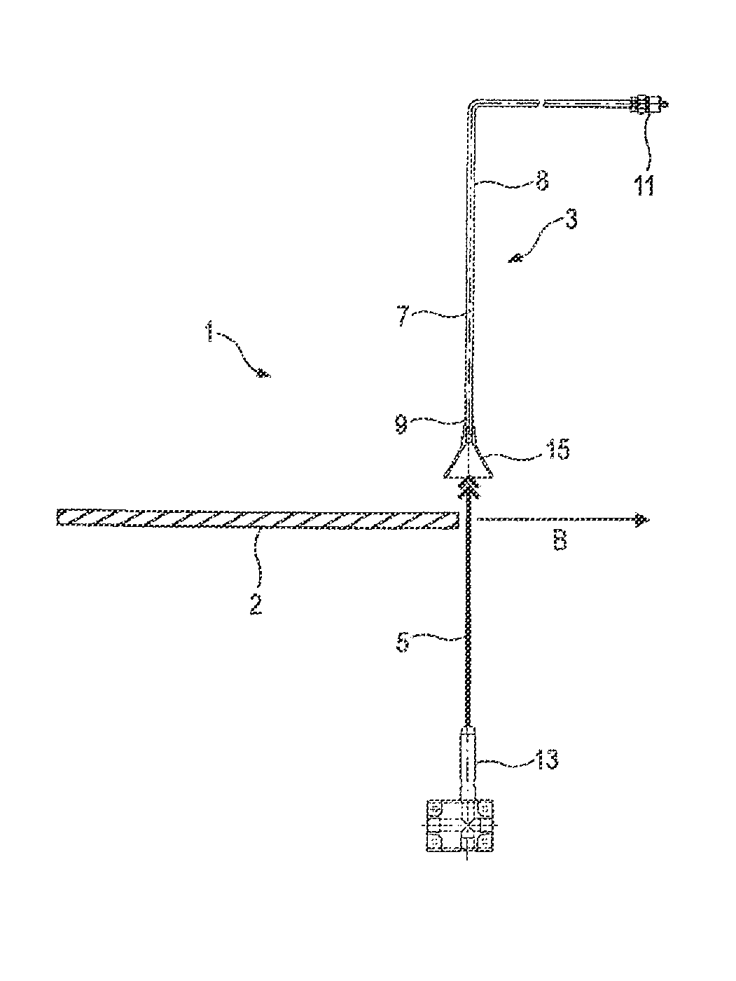
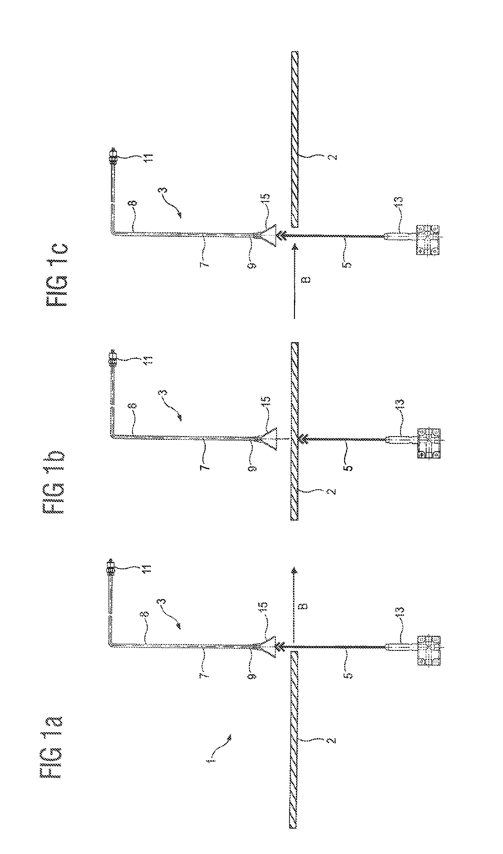
[0034]FIG. 1a shows an exemplary embodiment according to the invention of a device 1 for detecting a metal strip 2 or plate 2 in a strip-processing facility. The device 1 can be arranged at a control point or form such a control or synchronization point. As shown, a strip 2 is moving preferably in the direction B. The movement is not limited to one orientation, however. Reverse directions of the strip 2, such as those occurring in reversing mills, for example, are also possible. The strip 2 can also move along a curved or vertical path. For detection of the strip 2, preferably a fluid jet 5 is directed onto the (designated) path of movement of the strip 2. The fluid jet 5 can comprise gases, liquids, or mixtures thereof. The jet 5 is preferably produced by a nozzle 13, and as the jet travels vertically upward, it can strike the strip 2 passing the control point. Other orientations, however, are also possible.

[0035]The device 1 according to the invention also comprises a detection de...


PUM

PropertyMeasurementUnit
diameteraaaaaaaaaa
diameteraaaaaaaaaa
distanceaaaaaaaaaa

Abstract

A device for detecting the presence of rolling or cast stock, more particularly a metal strip or plate, in a casting, rolling or other strip processing facility, wherein the device includes a detection device for detecting a fluid jet which indicates the presence of the rolling or cast stock. The detection device in turn has an air-filled cavity, which has a tubular opening, and a pressure sensor for detecting an air pressure change in the cavity when the fluid jet hits the tubular opening. A corresponding method for determining the position of rolling or cast stock, more particularly a metal strip or plate, which moves through a casting, rolling or other strip processing facility.

Description

AREA OF THE INVENTION[0001]The invention pertains to a device for detecting the presence of rolled or cast stock, especially a metal strip or plate, in a position in a casting, rolling, or other type of strip-processing facility. In other words, the invention pertains to a device for detecting rolled or cast stock moving through a casting, rolling, or other type of strip-processing facility. Such a facilities can also be understood to consist of straightening machines or cooling linesPRIOR ART[0002]Especially in plate cooling units for large plates, synchronization points (“sync points”) are used within the installation as a means of keeping track of the material. These points have consisted up to now of, for example, a water nozzle underneath the plate or roller table and a type of cup, which is raised by the jet of water. The raised position is detected by a limit switch. When a plate is being transported through the machine, the water jet is interrupted by the plate. As a result,...

Claims


Application Information

Patent Timeline
Patent Type & Authority Applications(United States)
IPC IPC(8): G01D21/00B65G13/02
CPCB65G13/02G01D21/00B21C51/00B21B38/00B21B39/00B21B2273/18B65H7/02
Inventor GROSSE LORDEMANN, FREDERIK
Owner SMS GRP GMBH
Learn More