
Fan system

Inactive Publication Date: 2015-01-01
ASIA VITAL COMPONENTS SHENZHEN CO LTD
View PDF6 Cites 4 Cited by
  • Summary
  • Abstract
  • Description
  • Claims
  • Application Information

AI Technical Summary

Benefits of technology

The present invention provides a fan system capable of monitoring fan operation, sensing temperature and vibration, and actively warning if there is an abnormal state that may lead to fan operation failure or costly maintenance. This system ensures that fans operate efficiently and safely, reducing maintenance costs and avoiding fan operation failures.

Problems solved by technology

The accumulated heat results in a relatively high temperature at these areas and can not be easily dissipated from the closed communication chassis and server cabinets.
When the temperature exceeds the range that can be tolerated by the electronic elements of the communication apparatuses and the server appliances, the reliability or service life of the communication apparatuses and the server appliances would be seriously adversely affected.
That is, the temperature distribution in the conventional communication chassis and server cabinets is extremely uneven to largely reduce an overall heat dissipation performance of the communication chassis and the server cabinets.
However, these solutions would inevitably result in bulky and heavy communication chassis and server cabinets.
Under this situation, in the event of any damaged cooling fan in any of the communication chassis and the server cabinet, it would be difficult for a maintenance person to reach the site at once and replace the damaged fan with a new one.
When any of the communication chassis or the service cabinets sounds a warning or becomes out of order due to failed heat dissipation thereof, it also means that the fan in the communication chassis or the server cabinet is no longer workable and the electronic communication apparatus or the server appliance in the chassis or the cabinet might have become damaged and require repair.
Therefore, increased maintenance cost is required for the communication apparatuses and server appliances that are mounted in closed communication chassis and server cabinets that use conventional fans as the means of heat dissipation.

Method used


Image

  • Fan system
  • Fan system
  • Fan system

Examples


Embodiment Construction

[0015]The present invention will now be described with some preferred embodiments thereof and with reference to the accompanying drawings. For the purpose of easy to understand, elements that are the same in the preferred embodiments are denoted by the same reference numerals.

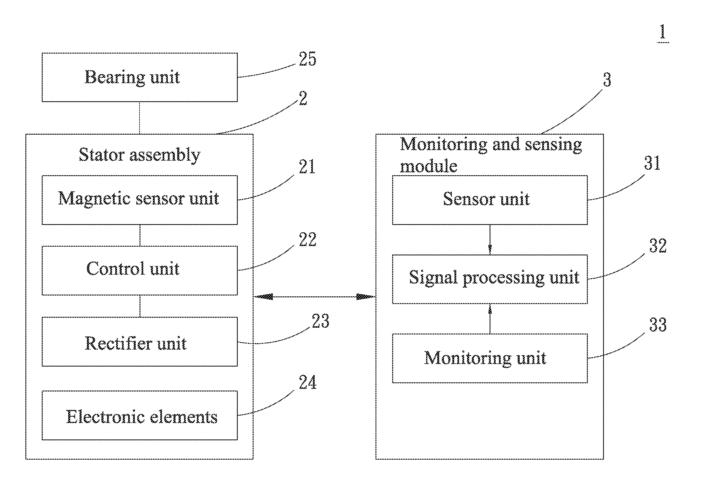
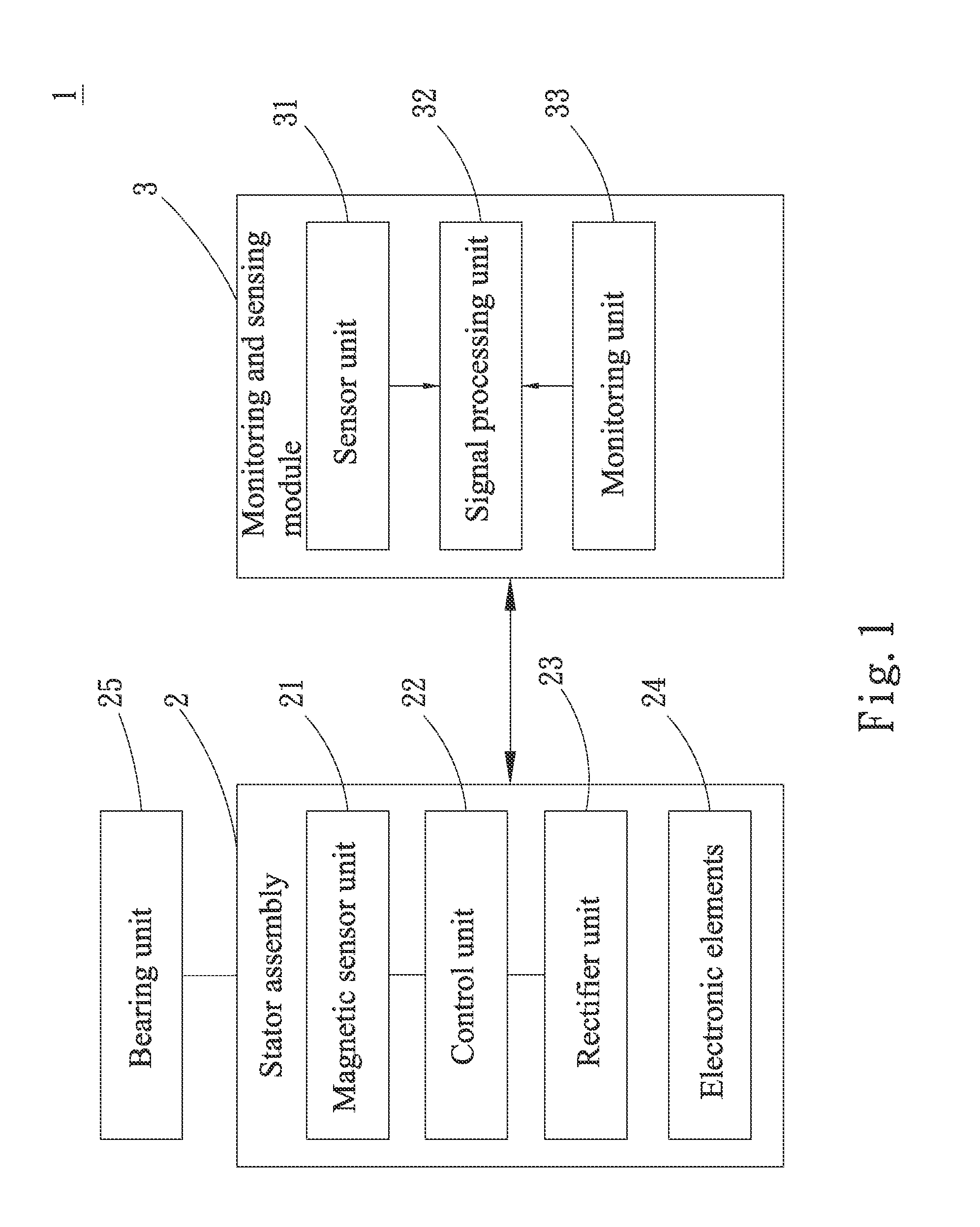
[0016]Please refer to FIG. 1, which is a block diagram of a fan system 1 according to a first preferred embodiment of the present invention. As shown, the fan system 1 in the first preferred embodiment includes a stator assembly 2 and a monitoring and sensing module 3.

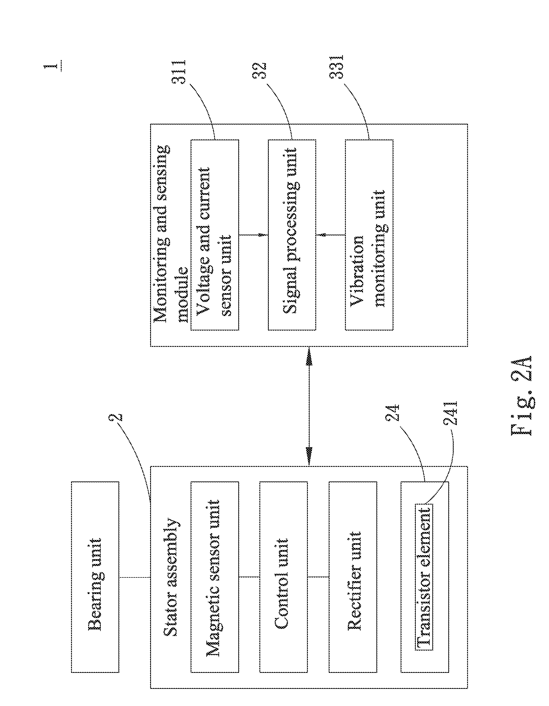
[0017]The stator assembly 2 includes a magnetic sensor unit 21, a control unit 22, a rectifier unit 23 and a plurality of electronic elements 24, and is provided with a bearing unit 25. In the first preferred embodiment shown in FIG. 1, the magnetic sensor unit 21 is a Hall element and is electrically connected to the control unit 22; the control unit 22 is a microcontroller and is further electrically connected to the rectifier unit 23; and the r...


PUM


Abstract

A fan system includes a stator assembly and a monitoring and sensing module. The stator assembly is electrically connected to the monitoring and sensing module, and the latter includes at least one sensor unit, at least one monitoring unit and a signal processing unit. The sensor unit of the monitoring and sensing module senses an operating state of the fan system, and the signal processing unit processes the sensing results of the sensor unit and actively generates a warning in the event of an abnormal operating state of the fan system, so as to protect the fan system against an operation failure due to any abnormal operating state and thereby reduce the fan system's maintenance cost.

Description

FIELD OF THE INVENTION[0001]The present invention relates to a fan, and more particularly to a fan system capable of actively generating a warning in the event of an abnormal operating state of the fan to avoid a fan operation failure and reduce fan maintenance cost.BACKGROUND OF THE INVENTION[0002]It is known that electronic communication apparatuses and server appliances are normally enclosed in individual communication chassis and server cabinets, respectively. When the electronic elements in the communication apparatuses and the service appliances operate, they produce heat at the same time. Since the communication chassis and the server cabinets are closed enclosure, the heat produced by the electronic elements of the communication apparatuses and the server appliances during operation thereof tends to accumulate and gather at some particular areas in the communication chassis and the server cabinets. The accumulated heat results in a relatively high temperature at these areas ...

Claims


Application Information

Patent Timeline
IPC IPC(8): F04D27/00
CPCF04D27/001
Inventor TSANG, SUNG-HSIANGLIN, YU-ANLIAO, YI-HONG
Owner ASIA VITAL COMPONENTS SHENZHEN CO LTD
Learn More