
Solid state circuit-breaker switch devices

a circuit breaker switch and solid state technology, applied in the direction of high-tension/heavy-dress switch, electrical apparatus, electrical arrangements responsive to excess voltage, etc., can solve the problem of mosfets experiencing large overvoltage spikes, devices exceeding peak current and/or continuous thermal rating, and higher thermal impedance of packaged devices

Active Publication Date: 2015-01-01
HAMILTON SUNDSTRAND CORP
View PDF8 Cites 11 Cited by
  • Summary
  • Abstract
  • Description
  • Claims
  • Application Information

AI Technical Summary

Benefits of technology

The patent describes a circuit that includes a SiC MOSFET device, a silicon based IGBT device, and a diode. This circuit is designed to prevent voltage from exceeding the maximum blocking voltage of the switch and to limit voltage transients at load turn-off conditions. The technical effect of this invention is to improve the reliability and efficiency of power switching circuits.

Problems solved by technology

However, during overload transient conditions MOSFETs may be subject to current unbalance that can cause the device to exceed its peak current and / or continuous thermal rating.
However, their relatively small size in comparison with silicon devices for the same rated power increases their heat flux and results in a higher thermal impedance of the packaged device.
Moreover, during turn-off events SiC MOSFETs can experience large overvoltage spikes due to their very fast turn-off time and can require additional voltage clamping devices, e.g. snubbers and Zener diodes.

Method used


Image

  • Solid state circuit-breaker switch devices
  • Solid state circuit-breaker switch devices
  • Solid state circuit-breaker switch devices

Examples


Embodiment Construction

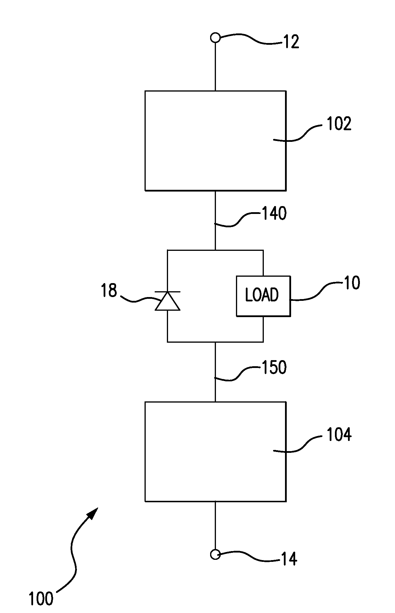
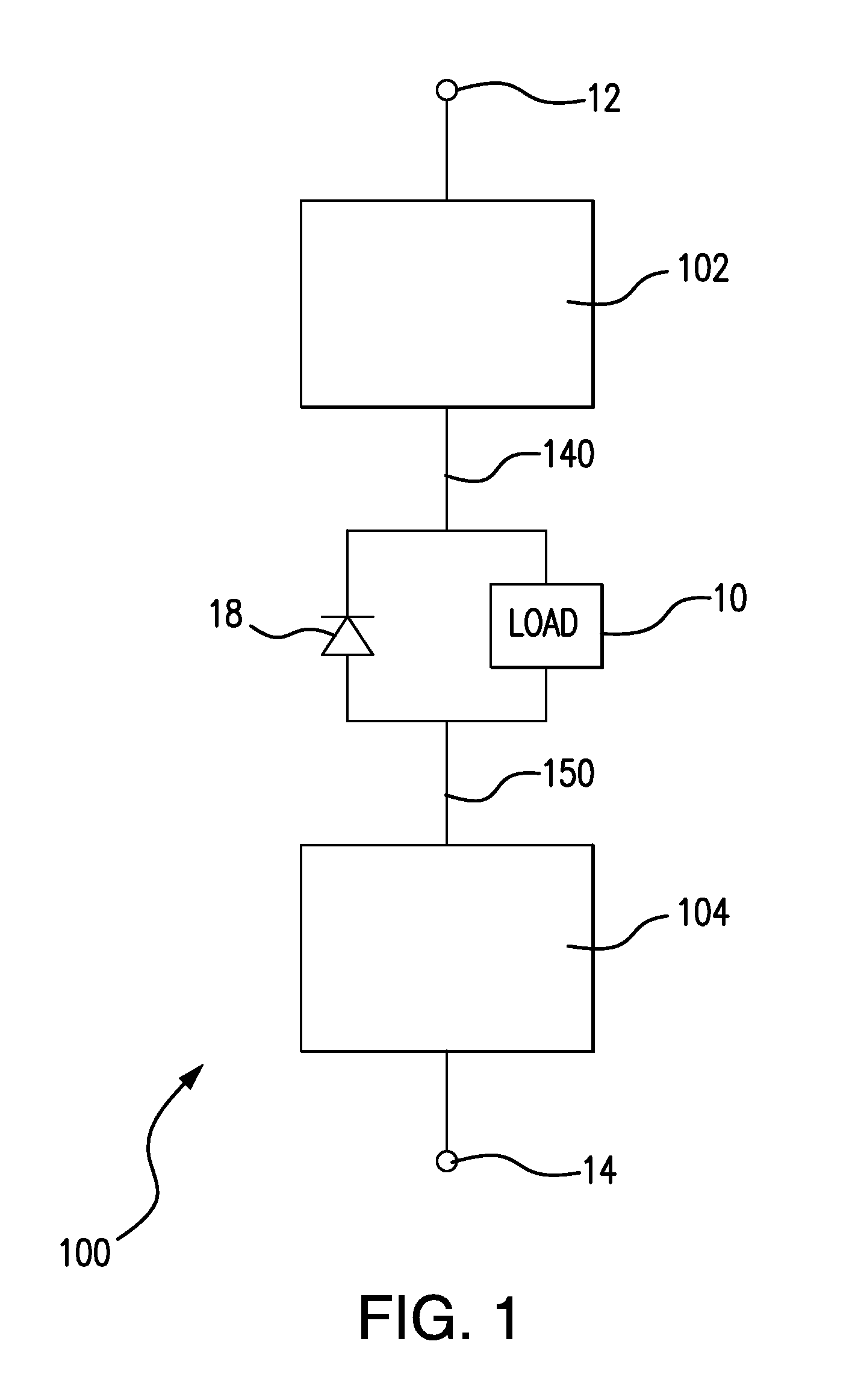
[0025]Reference will now be made to the drawings wherein like reference numerals identify similar structural features or aspects of the subject invention. For purposes of explanation and illustration, and not limitation, a view of an exemplary embodiment of an SSCB switch in accordance with the invention is shown in FIG. 1 and is designated generally by reference numeral 100. Other embodiments of the SSCB switch in accordance with the invention, or aspects thereof, are provided in FIGS. 2-9, as will be described. The systems and methods of the invention can be used for high voltage DC power management and power distribution, such as in hybrid vehicles for example.

[0026]SSCB switch 100 includes a first solid state switch 102 configured and adapted to connect to a positive terminal 12 of an HVDC power source. SSCB switch 100 also includes a second solid state switch 104 connected in series with first solid state switch 102 and configured and adapted to connect to a return terminal 14 ...


PUM


Abstract

A solid state circuit-breaker switch has a first solid state switch coupled to a positive terminal of a high voltage source, a second solid state switch coupled to a return terminal of the high voltage source, and a diode connected between the switches. A load is coupled between the switches and in parallel with the diode such that voltage transients across the load are limited during turn of conditions. Related methods of operating the switch during turn-on and turn-off events within rated current operation are described, as are turn-on and turn-off events in overload conditions.

Description

BACKGROUND OF THE INVENTION[0001]1. Field of the Invention[0002]The subject invention relates to solid state circuit-breaker switches, and more particularly to solid state circuit-breaker switch devices having a first switch arranged between a load and a positive terminal and second switch arranged between the load and a return terminal.[0003]2. Description of Related Art[0004]Hybrid electric vehicles utilize high voltage direct current power management and distribution. Solid state circuit-breaker (SSCB) switches are used in conventional power distribution systems to replace traditional electromechanical circuit-breakers. Their main functions are to distribute power to different loads. Compared to traditional electromechanical circuit-breakers, SSCB switches provide relatively fast response time, eliminate arcing during turn-off transients and bouncing during turn-on transients, and do not suffer performance degradation as a result of repeated fault isolation events. SSCB switches ...

Claims


Application Information

Patent Timeline
IPC IPC(8): H02H9/04
CPCH02H9/047H02H3/021H02H7/222H01H33/59
Inventor ROZMAN, GREGORY I.MOSS, STEVEN J.
Owner HAMILTON SUNDSTRAND CORP
Learn More